HOW TO MAKE ARDUINO TOLL TAX BARRIER
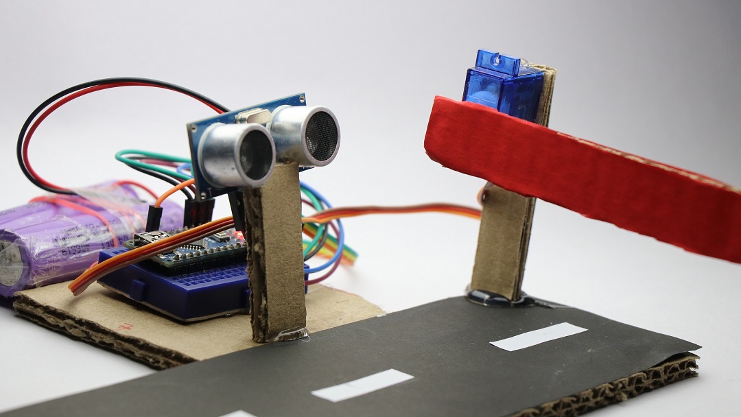
If you are searching for mini projects for engineering or if you are a student who is looking for Hobby project idea or best projects using Arduino
This can be easy and best Arduino project you can make on a budget, i.e Arduino toll tax barrier
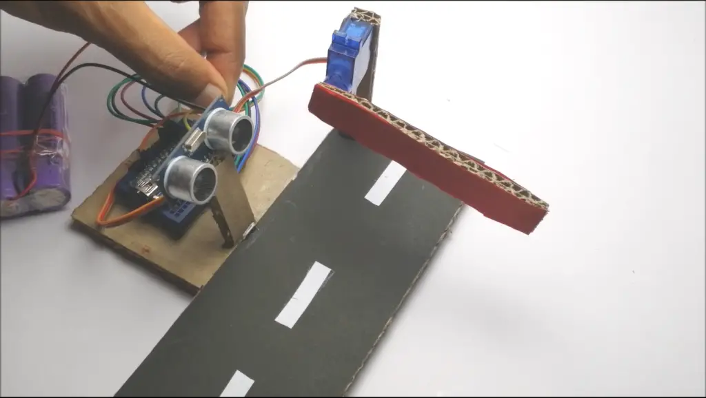
What is Toll Tax?
Some of the roads are managed by third party authorities, Hence if we want to travel through those roads which is well maintained or to compensate construction costs they charge us some money, so they stop us before entering the road and collect some money, since the number of vehicles passing through that road will be very high they need a form of a gate which is automated so that all the vehicle are stopped one after the other in a sequence.
Our version of Arduino toll tax barrier is made using some basic circuit in which we will be using ultrasonic sensor, micro servo, breadboard and few jumper wires
All codes are included here so anybody can make, this project can also be made in larger version and used as actual toll tax centers
So let’s begin making of this project in very detailed steps
Note: Video link is provided at the End
Principle of working in our Arduino toll tax barrier
Ultrasonic sensor is used to measure the distance between object
Here for demonstration I am using my hand
ultrasonic sensor is placed near the gate which will be raised/lowered when vehicle arrives
closed as vehicle departs Gate is attached directly to the shaft of micro Servo
whenever obstacle is detected by sensor, signals will be sent to Arduino board
Shaft of micro Servo lifts by 90°
we can also change the various parameters like the angle which should be raised by the micro servo also
At what distance ultrasonic sensor should start sending signal to the Arduino Nano or time of lifting and lowering barrier
Let’s start with the materials which is necessary to build this Arduino toll tax barrier,
Supplies for arduino toll tax barrier
Arduino Nano Get In INDIA / USA
Ultrasonic sensor Buy in USA / INDIA
Breadboard and jumper wires buy In INDIA / USA
Disclosure: These are affiliate links. As an Amazon Associate I earn some credits from qualifying purchases.
Circuit making
One of the main part in this project is building circuit,
Don’t worry if you are beginner I have explained all steps in detail also I have included circuit diagram for best understanding.
Circuit diagram with description
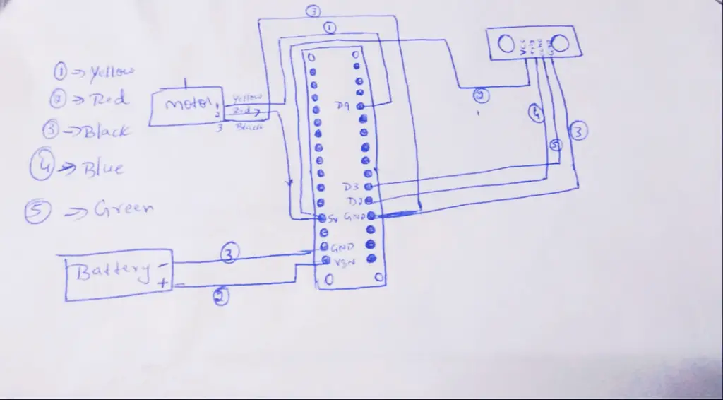
Micro servo connections
Micro Servo comes with three terminals, 2 for power supply and one will be for signal input, in my type of micro Servo there are yellow,red and brown wires.
Red for positive power supply brown for negative power supply and yellow for signal input.
From sensor vcc will be for positive power supply, Gnd will be for negative power supply
Trig and echo will be for transmitting and receiving echo signals
For controlling micro Servo rotation I am using , D9 pin from arduino Nano
To control the transmitting and receiving of ultrasonic sensor Signals i am using D2 and D3 pins
positive and negative power supply will go with + 5 volt and gnd board of Nano
To power this project, you can either use a USB power supply or rechargeable battery like I am using in this project.
NOTE: you can also eliminate use of breadboard and jumper wire by connecting the hardware components directly to the arduino nano board(soldering)
Once all circuitry is complete the project will look like in image below
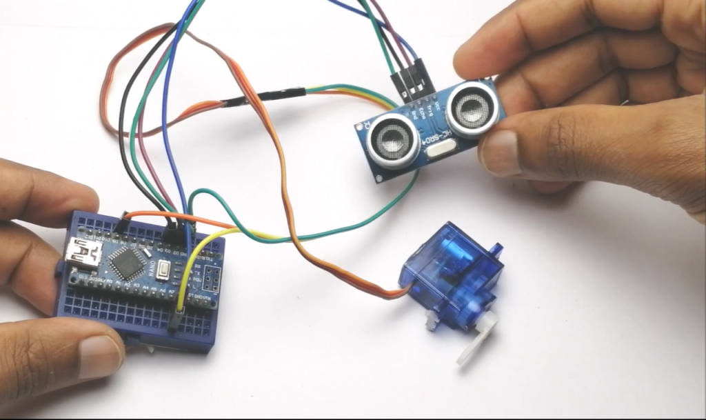
Now we need to upload specific set of codes to board using Arduino IDE software
Don’t worry I have written the codes for you!
DOWNLOAD CODE FROM HERE!
Just copy and paste it to your Arduino IDE if you have any issues let me know in comments
If you don’t have the Arduino IDE installed you can download it for free! also you can download the application from Play Store if you are using phone/tablet. it’s free application
I will be using computer to upload code
If you don’t have computer, use your smartphone only you need OTG cable and Arduino IDE application.
Once the uploading of code is complete, test it out by giving power supply
when you bring Hand/small toy vehicle near ultrasonic sensor micro servo will start making some movements
The rotation of angle depends upon the values given in the code.
Making Pathway for toll tax machine
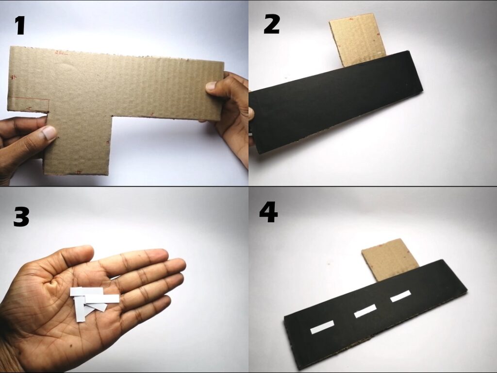
I am using piece of cardboard which looks like the letter T refer images above
To get the exact similar pattern of road i use black paint and few pieces of paper strips
All this shown in detail from image number 1-4
Now for the remaining part let’s make structure/frame which looks similar to the toll tax barrier
I will be using pieces of cardboard to make the outer frame you can also use MDF board,plastics or plexiglass instead of cardboard
You can draw and cut your own dimensions in the cardboard, just make sure all the cuttings are slightly larger than the size of the standard electrical components which we will be using
Assembling electronics
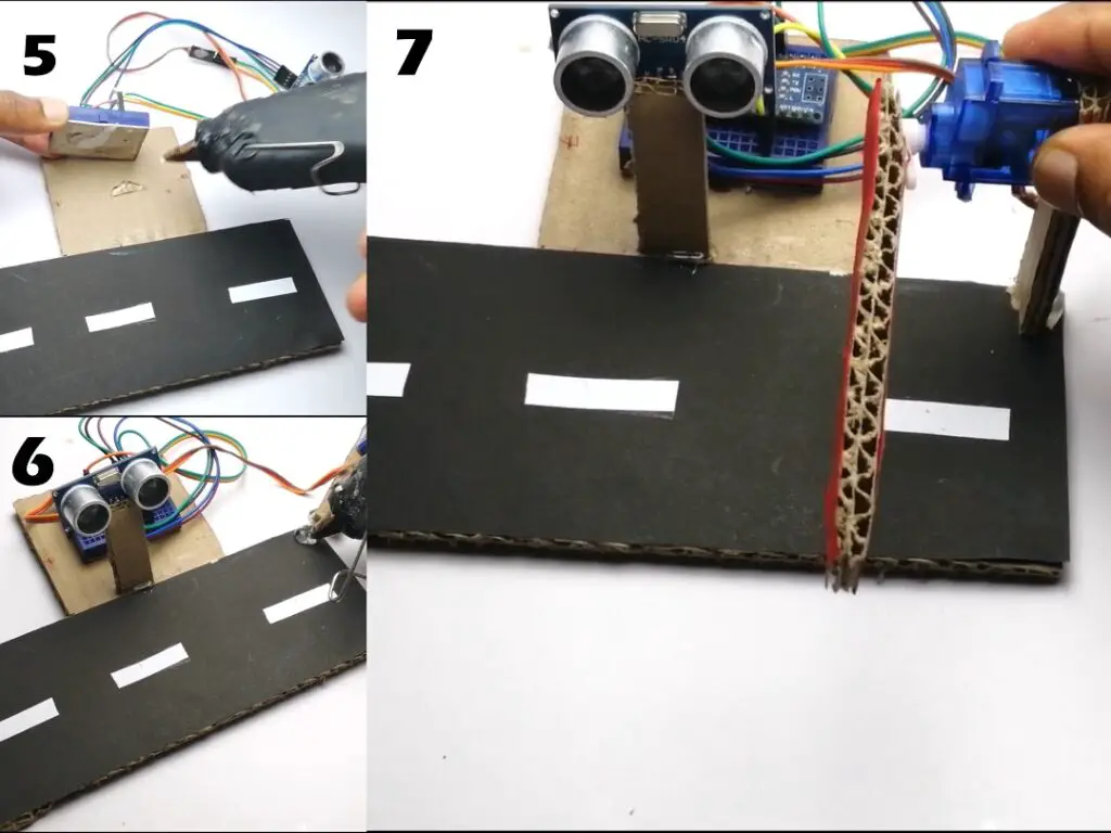
In Image number 5 you can see that using hot glue iam sticking breadboard to the cardboard frame
Image number 6, I am making space for ultrasonic sensor
You can place micro servo as per your convenience
Cut long rectangular piece of cardboard
paint with red/black color and couple it with shaft of servo as image number 7 for gate
Once these are finish connect batteries (u can use direct USB supply to Arduino board also)
I prefer using battery which are rechargeable(lithium ion) so that u can use this for long run
VIDEO LINK
Video for Arduino toll tax barrier making and working video
Now this project is ready for use
Note: You can also replace this small and light weight micro servo with larger metal geared micro Servo for bigger scale project
This was all about this project, if you have any queries or suggestions for improvements you can let me know in the comments.

