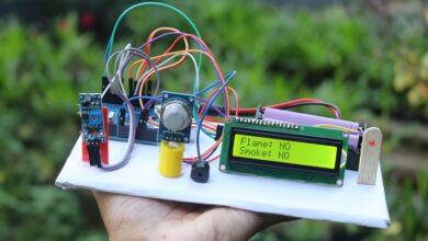
Arduino water level indicator project
Hello people in this post we will see how to make Arduino water level indicator project using ultrasonic sensor and LED.
This is a very useful project and there are many customisations that you can do as per your needs.
To begin with let me tell you how this project works!
The ultrasonic sensor senses the water level on the glass and indicated the level using 4 different LED.
Each LED indicates the level of water, first led indicates 0-25%, second one 25 to 50% similarly the third 50-75% and last one 75% to 100%.
The best part is this project works in real time, upon pouring or draining the water the led indicator changes as per the level sensing by the hcsr04.
Looking for Video tutorial of this project? Its in Jeevan Jee youtube Channel.
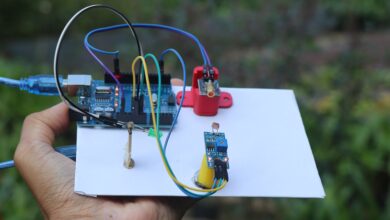
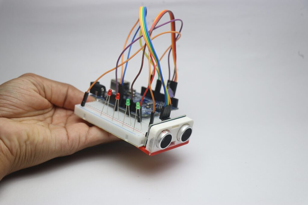
To build this project you need arduino uno, ultrasonic sensor, 4 leds, jumper cables and breadboard.
Water Level Indicator using Arduino Circuit Diagram
To begin with let me tell you how to make circuit for water level indicator.
Circuit is pretty simple, Connect the ultrasonic sensor Vcc and Gnd to 5v and ground pins on Uno board.
Trig and Echo pins are connected to D9 and D10 pins.
There are 4 leds and the negative leg is connected to Gnd power rail on breadboard and then to Gnd on the Uno.
Positive leg of LED to D2,D3,D4 and finally D5 and this is arranged in ascending order of water level.
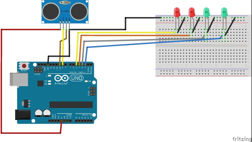
The power rails on breadboard is connect to the uno board for power supply.
After this is complete you can program uno board and lets see how that is done.
Arduino Water Level Sensor Code
This is the code for water level indicator project, Open your IDE and simply paste this program.
If you are familiar with program you can change various factors like blink speed of LED or lets say the brightness.
#define trigPin 9
#define echoPin 10

#define led1 2   // 0–25%
#define led2 3   // 26–50%
#define led3 4   // 51–75%
#define led4 5   // 76–100%

float duration;
float distance;
float levelPercent;
const float tankHeight = 10.0;  // glass height in cm
const float minDistance = 2.0;  // sensor cannot detect below this (adjust if needed)

void setup() {
  pinMode(trigPin, OUTPUT);
  pinMode(echoPin, INPUT);
  pinMode(led1, OUTPUT);
  pinMode(led2, OUTPUT);
  pinMode(led3, OUTPUT);
  pinMode(led4, OUTPUT);
  Serial.begin(9600);
}

void loop() {
  // --- Measure distance ---
  digitalWrite(trigPin, LOW);
  delayMicroseconds(2);
  digitalWrite(trigPin, HIGH);
  delayMicroseconds(10);
  digitalWrite(trigPin, LOW);

  duration = pulseIn(echoPin, HIGH);
  distance = (duration * 0.0343) / 2; // cm

  // Clamp readings within range
  if (distance > tankHeight) distance = tankHeight;
  if (distance < minDistance) distance = minDistance;

  // --- Calculate percentage with calibration ---
  levelPercent = ((tankHeight - distance) / (tankHeight - minDistance)) * 100;
  if (levelPercent > 100) levelPercent = 100;
  if (levelPercent < 0) levelPercent = 0;

  Serial.print("Distance: ");
  Serial.print(distance);
  Serial.print(" cm | Level: ");
  Serial.print(levelPercent);
  Serial.println(" %");

  // Turn off all LEDs first
  digitalWrite(led1, LOW);
  digitalWrite(led2, LOW);
  digitalWrite(led3, LOW);
  digitalWrite(led4, LOW);

  // Blink appropriate LED
  if (levelPercent <= 25) {
    blinkLED(led1);
  }
  else if (levelPercent > 25 && levelPercent <= 50) {
    blinkLED(led2);
  }
  else if (levelPercent > 50 && levelPercent <= 75) {
    blinkLED(led3);
  }
  else if (levelPercent > 75) {  // now triggers earlier
    blinkLED(led4);
  }

  delay(100);
}

// --- Blink Function ---
void blinkLED(int ledPin) {
  digitalWrite(ledPin, HIGH);
  delay(300);
  digitalWrite(ledPin, LOW);
  delay(300);
}
Since im using a glass of 10cm to test this project the program also follows the same calculations.
Once it is complete, Connect uno board to computer, Select proper board type and port then click on upload.
After the program is done uploading to Uno, You can arrange the components as shown in the project.
How to use arduino water level indicator project
There are multiple ways by which you can set this water level indicator.
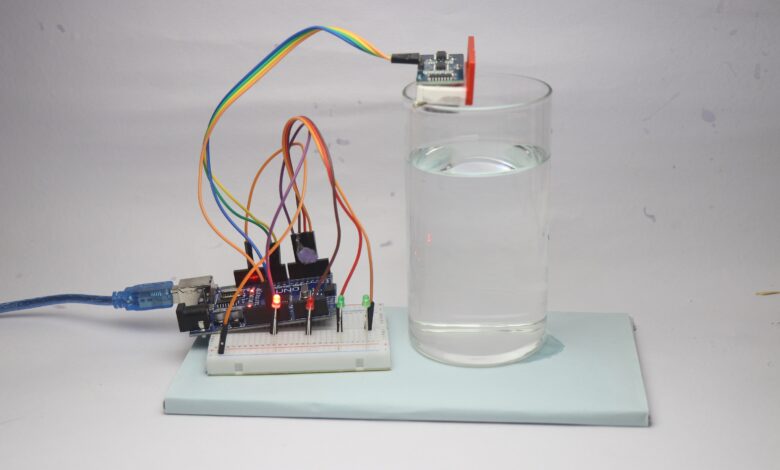
After the connections are done you will have project that looks like this.
I have added a 3d printed cover for the HC-SR04 so that it can be kept anywhere in the measuring object.
I used a glass and placed the sensor on top of that such that the sensor directly points out at the bottom of glass.
You may need to adjust untill you get a calibrated device.
Now connect uno to powerbank, you should see the last LED blinking when the glass is empty.
Start to pour water and now gradually as the level increases the next led starts to glow.
In the end when the glass is about to fill(~2cm gap) the last alert indicator led glows.
Consider adding a buzzer alongside the last led so that you can hear the buzzer sound and stop water supply.
This was all about this arduino based water level monitoring system, if you have any questions ask in the comments.
Interested in knowing more about how ultrasonic sensor works? You can check this post