How L298N Motor Driver works | How MPU 6050 Sensor Works
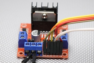
Hi, I have used l298n motor driver module in many of my projects, many might have been wondering How do this Motor Driver works, so I thought I would make a detailed instruction on How L298n Motor Driver Works, I bet after reading this many of your doubts will be cleared!
What is L298n Motor Driver

I would like to start by taking an example using LED, you can connect and use single LED on Arduino board without any issue but if you try to do same by running motor directly From Arduino Board it might Fry the chip of Arduino, Reason for this is motor draws high current when it undergoes some load.
So we can call l298N motor driver as Life saver as this module is for operating DC and stepper Motors with ease! IC used in this driver is called l298, this module can be used to control upto 4 DC Motors with speed and directional control.
How the H Bridge configuration works in L293N Motor driver
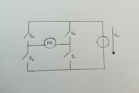
To control the speed and direction of a DC motor, L298n driver uses H Bridge configuration for those who don’t know How the H Bridge configuration looks like please refer images provided below.
Circuit diagram symbol meaning
Vin symbolizes input voltage while S1 S2 S3 S4 are switch and M symbolizes motor
Working of H Bridge
Working is very simple, when the switches S1 and S4 are switched on, Left side of motor becomes more positive compared to right terminal hence the motor rotates in one direction.
Meanwhile when switches S2,S3 are on, Right side of motor becomes more positive compared to left motor terminal so the motor rotates in other direction.
Features of L298n Motor Driver
Operating voltage is 40v( nobody uses such voltage) only 12v is used in 99% of projects
Heat sink for better cooling when IC heats up as Operating voltage is 40v
Pins
- 12 volt this pin is used for input from DC power source
- 5 volt for switching logic circuit theory inside by supplying power
- Gnd is used as ground pin
- Output 1 and output 2 will be the output pins of motor 1
- Output 3 and output 4 will be output pins of motor 2
- To enable Pwm (pulse width modulation) signal for motor 1 ENA used
- To enable Pwm signal for motor 2 ENB used
- In1 and 1n2 input pins for motor D1 also used to control the spinning direction and speed of motor
- In 3 and 4 will be input pins for motor to used to control speed and direction of motor 2
- Output 1, 2 motor 1 output pins
- Output 3 ,4 Motor 2 output pins
Applications of l298n motor driver
Mainly used to control speed and direction of DC motor in Robots and robotic cars motor controls and For the various projects which I have done using this motor driver please check out Arduino project section
I have provided basic information which were sufficient to understand the working of l298n motor driver, so that you will not face any issues while building projects using this motor driver, if you have any other additional information which might missed here, Don’t forget to share using comments box.
Now let’s Look into working of MPU6050 Which is one of most affordable and loaded with features sensor module.
Video shows working
Watch here to check How L298N Motor driver works was understood which lead to various projects
How MPU 6050 Works
MPU 6050, Well known by other names such as gyro sensor while some call it as motion sensor but technically speaking it has built in Accelerometer, Gyroscopic and Temperature Sensor stuffed in that small piece of board, it’s 6 axis motion sensing device, this digital device having high accuracy, low power consumption and easily programmable.
The image and size comparison shown below by taking hand as reference
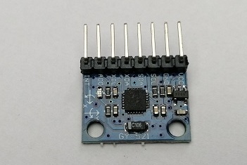
Pins and their functions in Gyro Sensor
- Vcc for power supply (positive)
- Gnd for power supply (negative)
- SCL for serial clock, provides clock pulse for I2C communication
- SDA for serial data pin, transfers data through I2C communication
- XDA for auxiliary serial data, to interface with other I2C Modules
- XCL for auxiliary serial clock, same as above
- AD0 for I2C address select, meaning if multiple gyro sensors used this pin helps in varying the address
- INT for interrupt digital output pin, indicates MCU that data made available to be read
Features of MPU6050
Uses 3v to 5v power supply and has I2C protocol for communication
3 axis gyroscope and accelerometer combined values gives High accuracy
Inexpensive and No sensor available with such features compared to price as result Endless projects can be build as it is Easy to work
Components in board
- Temperature sensor(digital output) and C106 Capacitor, Internal clocking’s, Gyroscope and accelerometer
- Digital motion processor(on chip) and Status registers
If u bought new MPU 6050 sensor and if u have Arduino Uno you can check yaw, pitch and roll data in serial monitor
Steps to check various parameters
Connect Vcc from sensor to 5v pin of uno
Gnd to Gnd-SCL to A5-SDA to A4 and INT to D2
Once u complete this basic connection, connect uno to computer then open arduino IDE from menu goto file->examples->MPU6050 and upload the code
Once code uploaded successfully
Open serial monitor and manually set baid rate to 115200 when you do this data will be printed on screen in real time, move your sensor in different direction to observe variant values
Applications of MPU6050
It’s difficult to point out few specific applications but in general Used in drones for maintain and balance position of drones
I use this to make self balance robot that detects rotation and orientation
3 dimensional mouse use this which use in gaming equipment/controllers and Gesture controlled gadgets
Robotic arms and in Humanoids
Well I hope I covered all the necessary topics needed to understand creamy layer working of MPU 6050 sensor which is enough to build various innovative projects, if you are eager to know much more deeper let me know in comments I will write separate in depth article on that topic.

