What is Silicon Controlled Rectifier (SCR), Working & Applications
The Silicon Controlled Rectifier (SCR) also known as Thyristors and is a crucial semiconductor component with many electronics and power management applications.
Its unique voltage-current qualities make it versatile in power control.
In this Post ]we will see SCR’s construction, working principles, silicon controlled rectifier circuit and wide range of applications, focusing on its voltage-current (VI) properties.
You might also like how tesla coil works
Construction of Thyristor
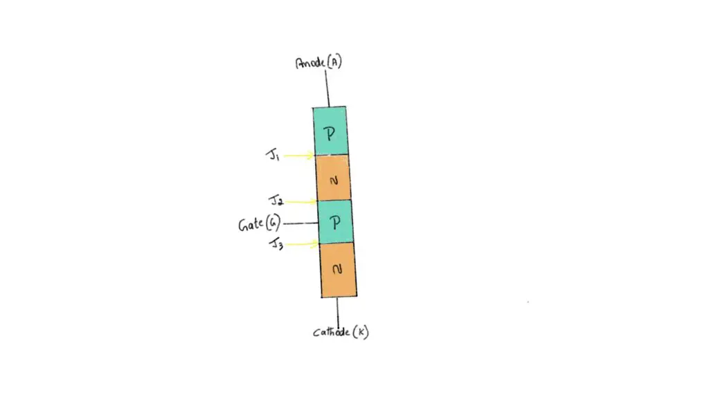
Let’s start with the SCR’s basic construction. It has three semiconductor layers, anode, cathode, and gate.
These layers are carefully built and doped to control electrical current flow.
The anode, the device’s output terminal, has positive charge, whereas the cathode, the input terminal, has a negative charge.
The gate, a conduction-starting control terminal, is between them.
Coming to silicon controlled rectifier definition. SCRs are bistable switches.
It stays non-conducting until the forward-break overvoltage applied across the anode and cathode.
When this voltage threshold is exceeded, the SCR rapidly conducts, enabling a lot of current.
This trait is important in situations that need precise power delivery control.
The SCR can continue conduction after the gate signal gone. Latching allows the SCR to stay “on” until the current through it decreases below a threshold, usually because of natural load conditions.
Silicon controlled rectifier circuit diagram
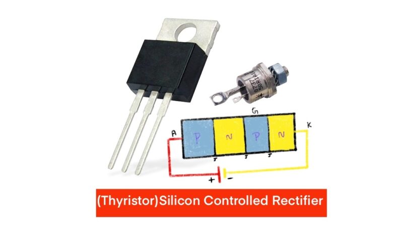
SCRs, or Silicon Controlled Rectifiers, are PNPN semiconductor devices with three layers and three terminals.
The device’s name comes from its silicon-based nature. and the silicon controlled rectifier symbol is similar to diode.
Anode (A)
The positively charged SCR anode is usually made of P-type silicon.
This vital component allows electric current into the device. The anode starts SCR conduction when an external voltage exceeds the forward-break over voltage threshold.
Cathode (K)
The cathode is negatively charged terminal in the SCR structure, unlike the anode.
It is made of P-type silicon like the anode. Current leaves the gadget through the cathode. This terminal is crucial to the electrical circuit.
Gate (G)
As SCR control terminal, the gate terminal is crucial. The device’s conduction is activated by the gate current at the interface.
The gate current activates the SCR, making it conduct.
There are three components anode, cathode, and gate terminals form the SCR.
The SCR’s special qualities come from the interaction between these components and the semiconductor layers’ PNPN structure, making it useful in many applications that need precise electrical current regulation.
The N-type layer between the anode and cathode is crucial to the SCR construction. This N-type layer creates the device’s first PN junction.
In addition to the N-type layer, the second PN junction has a P-type layer. SCR behavior is shaped by these two levels, N-type and P-type.
These semiconductor layers, each with unique electrical properties, plus the strategically placed anode, cathode, and gate terminals allow the SCR to control and regulate electrical current flow.
The N-type and P-type layers work together and the gate terminal controls the SCR to switch from non-conductive to conducting when needed. SCRs are essential in many applications that require accurate electric current control due to their nature.
The vi characteristics of silicon controlled rectifier explain its response to voltage (V) and current (I) fluctuations. These VI traits are key to understanding SCR operations.
The SCR’s working concept in forward-biased and reverse-biased modes will be explained step by step.
Forward-Biased Mode
A positive voltage on the anode (A) concerning the cathode (K) biases the first PN junction in the forward-biased mode. Initially, the SCR is off, blocking current flow from the anode to the cathode.
A tiny current is applied to the gate (G) terminal to turn the SCR on. Gate current is crucial to device triggering.
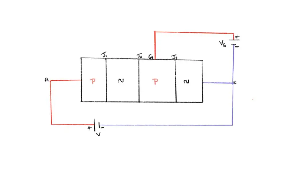
The SCR blocks current when off due to its high resistance. However, gate current catalyzes a transition.
The SCR enters a low-resistance condition, allowing a large current to flow from A to K. This crucial change is the “ON” state or forward conduction state.
Interestingly, as per the characteristics of scr, the SCR stays ON after the gate current withdrawn. This property, latching, controls SCR behavior.
The SCR’s holding current must drop below a threshold to turn it off. SCRs are intriguing and useful in applications that need precise electrical current regulation because to this unique property.
Reverse-Biased Mode
The first PN junction becomes reverse-biased when a negative voltage is given to the anode (A) relative to the cathode (K), unlike the forward-biased mode.
In this mode, the SCR remains OFF, preventing anode-to-cathode current flow.
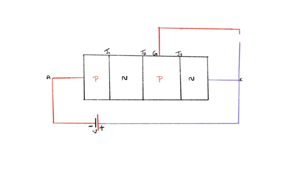
As per v i characteristics of scr, non-conductive is reverse-biased mode’s main property. The SCR blocks large currents with its high resistance. It is ideal for one-way current flow applications due to its properties.
Silicon Controlled Rectifiers use VI properties to precisely control electrical current flow. A positive anode voltage and gate current operate the SCR in forward-biased mode, turning it on with low resistance.
This state stays after gate current removal unless the current falls below the holding current threshold. In reverse-biased mode, a negative anode voltage keeps the SCR off, limiting current flow.
The SCR’s diverse modes and behaviors make it essential in many applications that require controlled electrical power conduction and switching.
SCR VI Characteristics: Understanding Behavior under Varying Conditions
The scr vi characteristics reveal its behavior under changing voltage and current settings. These properties reveal how this semiconductor device works from OFF to ON. Let’s explore these traits to understand the SCR’s behavior.
Off State: High Resistance and Blocking
In its off state, the SCR has a very high resistance, blocking electrical current from the anode (A) to the cathode (K).
This resistance results from a gate current below the triggering threshold. A negligible leakage current passes through the SCR in this state.
Most of the applied voltage is firmly blocked, demonstrating the SCR’s electrical circuit isolation.
Triggering: Initiating Conduction
A gate current above the triggering threshold triggers the SCR to turn on. The SCR is active by this gate current surge. After being active, the SCR quickly switches to ON, marking a crucial moment in its operation.
On State: Low Resistance and Sustained Conduction
From high-resistance OFF to low-resistance ON, the SCR changes dramatically. This transition lets the SCR conduct a lot of current without much voltage drop.
The gadget works well because the ON state has low resistance, allowing efficient conduction.
Latching is a fascinating SCR trait. The SCR stays ON after the triggering gate current withdrawn.
These scenarios usually include the SCR current decreasing below the holding current. This outstanding property makes the SCR highly reliable in applications that require continuous conduction.
Applications of Silicon Controlled Rectifier (SCR)
The Silicon Controlled Rectifier (SCR) known for efficiently switching high-power loads. Its versatility and exact conduction make it essential in many sectors. Let’s examine some key SCR applications:
Power Control
SCRs are essential in power control circuits because they regulate and manage electrical power. Dimmer switches use SCRs to smoothly and precisely alter lighting settings.
Many businesses use them to control electric motor speed and efficiency. SCRs also control heater and oven power in industry, ensuring accurate temperature control and energy economy.
Rectification
High-power rectification often uses SCRs to convert AC to DC. They efficiently convert and regulate electrical power for diverse uses in high-voltage power supplies and battery charging systems.
Voltage Regulation
In voltage control circuits, SCRs are essential for steady output voltages. They protect power supply and battery charging systems from voltage fluctuations.
Motor Control
Industries and transportation use SCRs for motor control. Electric trains, trams, and elevators use SCRs to control motor speed and operation, making them safe and efficient.
Welding Equipment
Electrical currents should precisely controlled in welding equipment. Welders need SCRs to achieve accurate and controlled current outputs to ensure weld quality and precision.
Voltage Clamping
SCRs defend electronic equipment against voltage spikes and surges in surge protection devices. Voltage clamping protects sensitive electronic devices from voltage fluctuations, protecting important equipment.
SCRs are versatile and essential semiconductor devices that precisely control electrical current conduction. Its VI features, which show its behavior under different settings, help explain its operation. SCR applications include power control, rectification, voltage regulation, and motor control, driving innovation, efficiency, and reliability in many sectors. Its special properties help companies and technologies survive in a world increasingly dependent on controlled and efficient power management.
why use silicon controlled rectifier
The scr v i characteristics shows that it is a useful semiconductor device for controlling and switching high-power loads. Since a PNPN structure with anode, cathode, and gate terminals.
In many industries and electronic systems, their capacity to handle high-power loads and provide precise control makes them essential for efficient and reliable operation.
Because of these features SCRs found in power control, rectification, voltage regulation, motor control, and welding.
You can also check our previous post on How machine leaning works