RFID Based Arduino Toll System with Circuit Diagram
Hello Friends in this project i will show you how to make RFID Based Arduino Toll System.
This is a very interesting project that you can make for your upcoming engineering project.
In this article we will see step by step instructions on making this RFID Based Arduino Toll System.
Before building this project let me explain in short about this project concept.
What is RFID toll gate system
RFID in short stands of radio frequency identification, this is a technology where there is a small tag.
Each tag has unique id like the finger prints, This ID activates the rfid module.
There is a communication between the transmitter and receiver part and in betweeen this we are using arduino Uno.
The Arduino program for rfid control the servo motor which will open and close the gate.
The logic is simple, when a registered tag is tapped on the rfid board, if the UID is already present the servo will be activated.
The servo horn is attached with gate/barrier and it will be opened, and the led turns green.
In the other case if the tag is not present in the program or not registered upon tapping the rfid tag the red led glows and gate remains closed.
This concept holds good to make rfid house door lock and such other projects.
Project materials for RFID gate with arduino and servo
- Arduino Uno
- Servo
- RFID module with tags
- Jumper wires
- Red and Green Led
- Lithium ion battery and holder
- Small switch
These are the only materials that you will need to make this useful Arduino project.
RFID Based Arduino Toll System circuit diagram
Here is the Rfid based arduino toll system diagram to make the circuit.
The circuit is easy to make and there is no need of any breadboard here.
Further to make it easier I will explain the circuit in steps.
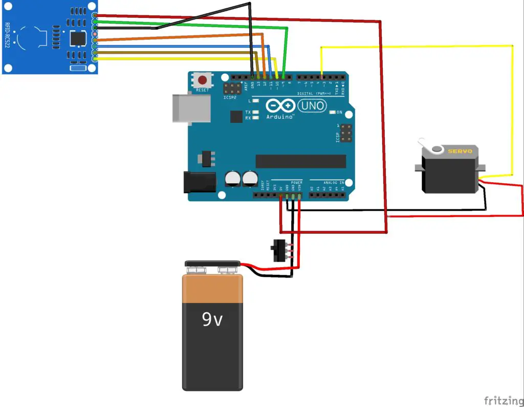
The micro servo signal pin to D3 pin of the Uno board.
The Gnd and Positive pin of servo is connect to gnd and 5v pin of Uno board.
The RFID Sensor module pins can be connect as follows
Sda to D10, Sck to D13, Mosi to D11 and Miso to D12
The power pin gnd to gnd and 3.3v from rfid to 5v pin of Uno
Rst pin to D9 and now the led color are red and green
Red and green positive side to D3 and D4
Note that the LED connections is not given in circuit so i have written it here.
The gnd of both Led to Gnd of Uno, To power this i will use 2 lithium ion batteries with switch control.
RFID Based Arduino Toll System Code
Arduino Program for this project is given here, If you know to make changes you are welcome to customize this.
If you are beginner i recommend to not to make any changes.
Just copy and paste this arduino progrem for RFID arduino project on your IDE.
Select the proper type of port, if you dont have RFID library get it here, MRFC522 Library for Arduino.
Extract the IDE, Select the port and upload the code.
Here you have to note that the UID of your and my tag are different, So to make this project work you have to enter your code.
How to read code from RFID Module using RFID tags
- Upload the code to Uno open the serial monitor.
- Now select the baud rate to 9600 and a message will pop up to tap the tag
- Now tap the tag on the MRFC522 board and a code will appear on the serial monitor.
- Copy this code and paste it on your Arduino program and reupload the code.
- After the code is uploaded successfully you can test the project.
How to Test the RFID Module tags
Power on the arduino uno board and check for the indicator light on the MRFC522 module.
Tap the registered tag and now the servo will move and the greem led will glow.
The servo opens and closes automatically, and the green LED will turn off.
Now try the same with unregistered tag, the RED LED glows and the servo doesnt open.
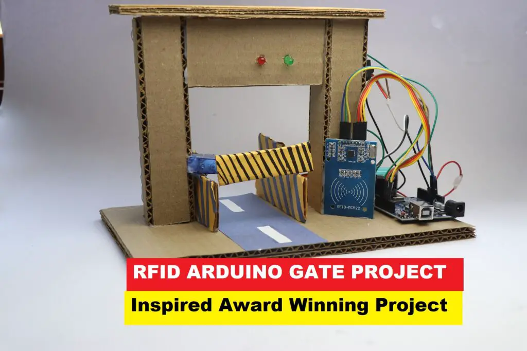
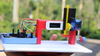
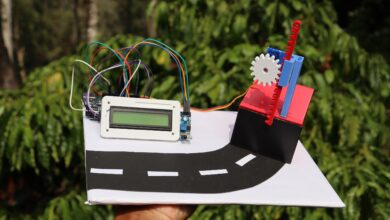
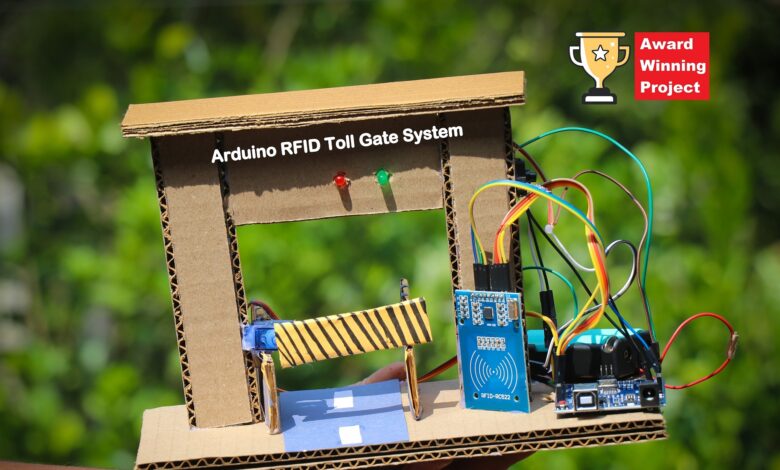
I will use the cardboard structure to make the project look like the actual toll gate system.
Use the strips of cardboard to make the structure like I did because it looks appealing.
This was all about this useful project using Arduino and RFID module.
If you have any questions ask us in the comments.
Working video of RFID toll system with arduino
You can watch how to program the Arduino Uno board for accessing RFID tags in this video.
Also don’t miss to check the circuit building for the LED here, i have not given that in the circuit diagram but is given in the video.
Here is the video of the build and the working of this project.