Arduino Battery Health Monitor DIY
Hello makers in this article i will show you how you can make arduino battery health monitor at your desk.
Being a hobbyist creator requires a lot of creativity and also lots of battery power!
Yes yes you heard it right the battery that powers your inventions, But have you ever thought to check on them?
Even batteries loose their backup time and we can call it as health and it is necessary to check that before you use them in any important project.
In this post i will make a battery health monitor and give all the necessary build steps to make them on your own.
Also watch this video of building this project.
You may be interested in my previous project on real time gas leakage monitoring system project
Materials for making battery health monitor
- Arduino Uno
- OLED Module
- Current Sensor 1na219
- Jumper Cables
- Pixel Ring(i used 8 bit)
- Battery and Dc motor
- 3d Printer
- PLA Filament
Design of frame
I will be 3d printing the frame for this device and you can see the design that i will be making in the below visual.
It was made using Tinkercad application and you can make this remix also.
Design looks simple but it is made after many trial and errors so that the end result is flawless.
There are only 2 parts that we will be requiring to make this monitoring device and you can use my design to 3d print this.
Design is simple and you can install all the components inside this.
After you have this design simply 3d print the parts and now you have the parts ready.
3D printing wont take any long time, and also there is no need to post process the parts after printing.
Circuit for Arduino Battery Health Monitor
This is the circuit that i will be using to make circuit for this project.
Here the OLED, Pixel ring and current sensor are one part of circuit.
Battery and motor will be the other part, since to measure the current we need load and the load is from motor.
Note that in the oled i missed to add the correct wires for power kindly reorder it for yourself(highlighted the correct order below in bold).
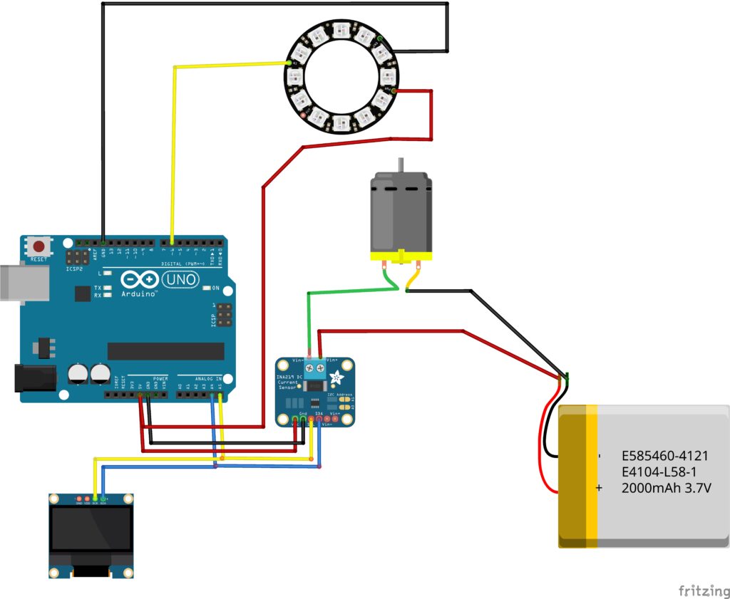
There are 4 pins on the OLED module
Scl and Sda from OLED and current sensor are connected to A4 and A5 pin on the Uno board.
Vcc and Gnd from OLED are connected to Vcc and ground on the Uno.
The Gnd and Vcc from current sensor is also connected to Arduino Uno.
Pixel ring signal or the Din is connected to D6 on the Uno board.
This completes the circuit part and now proceed to upload the program.
Open the arduino ide, select proper port and board and click on upload button.
Arduino Code for Battery Health Monitor
Use this arduino program inside your ide and upload it to the board.
There is no need to change anything you can copy and paste from this program page.
#include <Wire.h>
#include <Adafruit_INA219.h>
#include <Adafruit_NeoPixel.h>
#include <Adafruit_SSD1306.h>

#define LED_PIN 6
#define NUM_LEDS 8

Adafruit_INA219 ina219;
Adafruit_NeoPixel ring(NUM_LEDS, LED_PIN, NEO_RGB + NEO_KHZ800);
Adafruit_SSD1306 display(128, 64, &Wire);

float voltageFiltered = 0;
float alpha = 0.1;

bool systemReady = false;
int stableCount = 0;
int lastLevel = -1;

// -------- RAINBOW ANIMATION --------
void rainbowCycle(int wait) {
  for(long j = 0; j < 256; j++) {
    for(int i = 0; i < NUM_LEDS; i++) {
      ring.setPixelColor(i, ring.gamma32(ring.ColorHSV((i * 65536 / NUM_LEDS) + j * 256)));
    }
    ring.show();
    delay(wait);
  }
}

// -------- SETUP --------
void setup() {
  Wire.begin();
  ina219.begin();

  ring.begin();
  ring.setBrightness(12);
  ring.show();

  display.begin(SSD1306_SWITCHCAPVCC, 0x3C);
  display.setTextColor(SSD1306_WHITE);

  // -------- WELCOME --------
  display.clearDisplay();
  display.setTextSize(2);
  display.setCursor(10, 10);
  display.println("WELCOME");
  display.display();
  rainbowCycle(10);

  display.clearDisplay();
  display.setTextSize(1.5);
  display.setCursor(10, 25);
  display.println("Battery Checker");
  display.display();
  delay(1500);

  // -------- BOOT --------
  display.clearDisplay();
  display.setCursor(20, 25);
  display.println("BOOTING...");
  display.display();
  rainbowCycle(5);

  // -------- INITIALIZING --------
  display.clearDisplay();
  display.setCursor(10, 25);
  display.println("INITIALIZING...");
  display.display();

  // soft blue glow
  for(int i=0;i<NUM_LEDS;i++) {
    ring.setPixelColor(i, ring.Color(0,0,40));
  }
  ring.show();

  delay(1500);
}

// -------- LOOP --------
void loop() {

  float busV = ina219.getBusVoltage_V();
  float shuntV = ina219.getShuntVoltage_mV() / 1000.0;
  float loadV = busV + shuntV;

  // Validate readings
  if(loadV > 2.5 && loadV < 5.5) {
    voltageFiltered = (alpha * loadV) + ((1 - alpha) * voltageFiltered);

    if(abs(loadV - voltageFiltered) < 0.05) {
      stableCount++;
    } else {
      stableCount = 0;
    }
  }

  // -------- WAIT FOR LOAD --------
  if(stableCount < 10) {

    display.clearDisplay();
    display.setTextSize(1);
    display.setCursor(10, 25);
    display.println("CONNECT LOAD...");
    display.display();

    // breathing LED
    static int b = 5;
    static int dir = 1;
    b += dir;
    if(b > 25 || b < 5) dir = -dir;

    for(int i=0;i<NUM_LEDS;i++) {
      ring.setPixelColor(i, ring.Color(0,0,b));
    }
    ring.show();

    delay(100);
    return;
  }

  // -------- FINAL MODE --------
  float v = voltageFiltered;

  display.clearDisplay();

  display.setTextSize(2);
  display.setCursor(10, 0);
  display.print(v, 2);
  display.print("V");

  display.setTextSize(1);
  display.setCursor(0, 40);

  uint32_t color;

  if(v > 3.7) {
    display.print("Battery: GOOD");
    color = ring.Color(0,150,0);
  }
  else if(v > 3.4) {
    display.print("Battery: OK");
    color = ring.Color(150,80,0);
  }
  else {
    display.print("Battery: LOW");
    color = ring.Color(150,0,0);
  }

  display.display();

  int level = map(v * 100, 330, 420, 1, NUM_LEDS);
  level = constrain(level, 1, NUM_LEDS);

  if(level != lastLevel) {
    for(int i=0;i<NUM_LEDS;i++) {
      if(i < level) ring.setPixelColor(i, color);
      else ring.setPixelColor(i, ring.Color(0,0,5));
    }
    ring.show();
    lastLevel = level;
  }

  delay(200);
}
My number of leds on the pixel ring was 8 if you have different number change in the program and then upload.
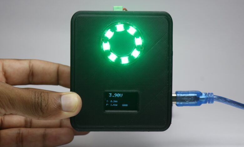
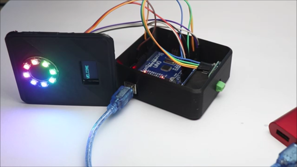
Once the upload part is complete you will start to see message on the oled and also the pixel ring light glows.
This is the circuit that i made following the circuit diagram and you can expect the same too
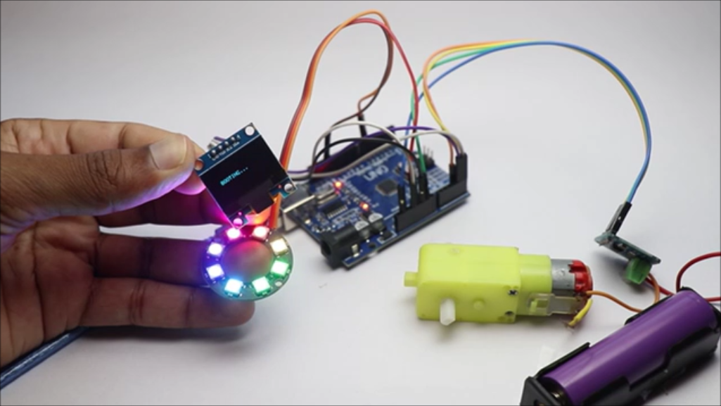
If you are in this step almost all the circuit seems to work correctly and now you can install all the electronics to 3d printed enclosure.
Now you can work on the casing part and finish the build part.
There is a small announcement that i would like to say here, if you don’t have a 3d printer you can get it done by the service from JLCPCB.
And also If you want to make this device more smaller you can use PCB and i would suggest JLCPCB for that.
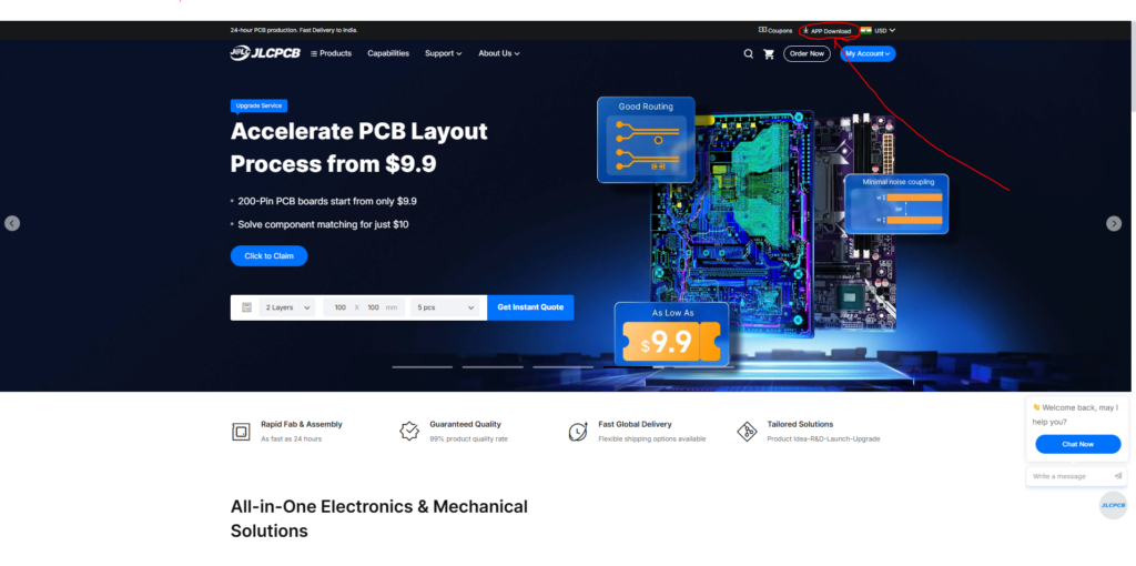
They have fast shipping with more affordable options, and now they have JLCONE which makes everything pretty much easier.
JLCONE is a application that is available for both desktop and mobile and you can manage your orders and other services in a single platform.

With the JLCONE you can manage everything on a single screen and save lots of your time. Try their services to know more.
Assembly and Using the Project
Now before joining the two halves make sure to check if nothing is left out at the time of assembly.
Jumper cables sometime come out and to verify this i will power the board and check.
After you have confirmed that this is working fine seal the 2 parts using super glue.
Gently press the parts so that the join is complete and no gaps left.
Now to test the project, Simply connect uno to power bank using the cable and you will see message on oled and ring light glows.
Now to check battery health connect one end of battery (positive) to the current sensor.
Connect the negative end of battery to positive side of load and negative side of load to sensor again,
This series circuit will help to distribute power flow and help sensor to measure battery health.
If the battery health is good the pixel light turns green and if the health of battery is poor the light glows red.
This is all about building this arduino battery health monitor, if you have any questions ask in the comments.
Here is the video of working from this project