Heart Beat Monitoring System using Arduino and Pulse Sensor
Hi makers in this post we will see how to make Heart Beat Monitoring System using Arduino or Arduino heart rate monitor with OLED and pulse sensor.
If you are planning to present this in your upcoming projects it’s a good choice! We have given all the circuit diagram explanations along with heartbeat sensor Arduino code and step-by-step build instructions.
Before diving into the build phase let me give you a quick overview of this project.
What is Arduino pulse Rate Monitor?
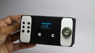
This is a USB powered or plug-and-play device that can show the rate of heartbeat very instantly as soon as the fingers are placed on the sensor.
This is an inexpensive project and is easy to build.
Since it’s a practical tool that everybody needs it’s worth a try to build this.
Note: You cannot completely rely on the results of this device as there are many factors that represent the device’s accuracy.
How Does Pulse Rate Monitor Works
This works on the very simple principle, To understand this we need to know how the pulse sensor works.
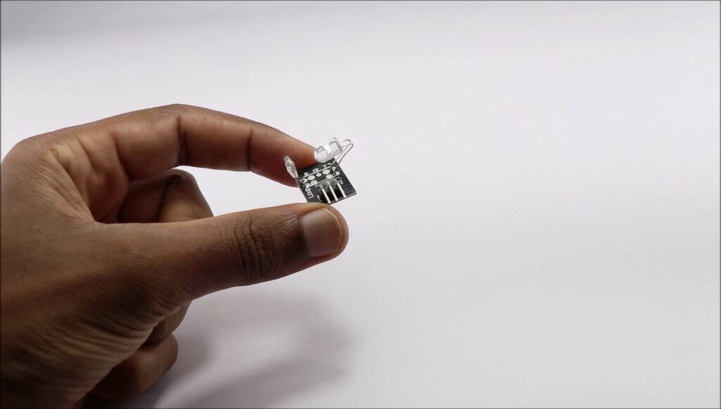
The pulse sensor for this project is shown in the visual above, there are various kinds that come with different accuracy levels.
I chose to use this, if it is an infrared type we are good to go.
You may wonder how this functions, well it is very simple.
It has an infrared LED transmitter and receiver bulbs embed on a PCB.
When we place our finger on top of this sensor, infrared light hits the blood vessels and later travels to the receiver.
This is the value that will be convert to BPM using codes.
This is the very basic principle behind this project, now we will see the build phase.
Materials
- Arduino Uno
- Pulse sensor and OLED module
- Jumper wires/single strand wires and breadboard
- Arduino IDE and programming cable
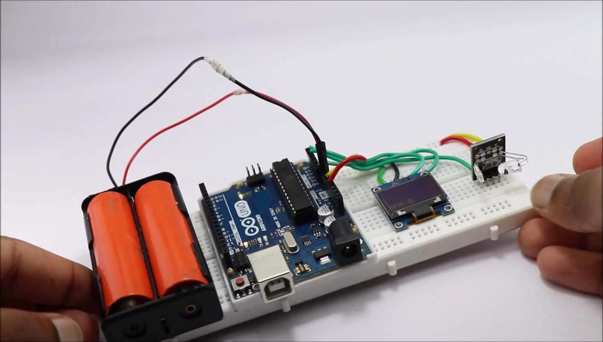
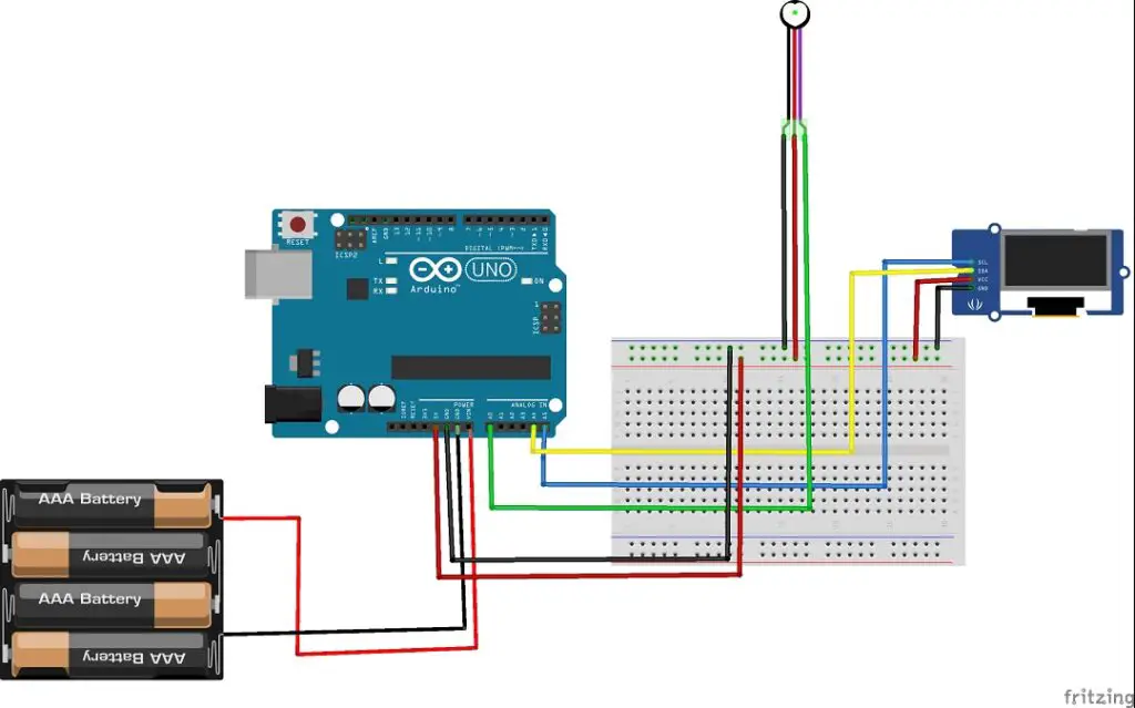
Circuit Diagram for Arduino based Heart Beat System
The Circuit diagram shows batteries that are powering this project, we can use USB too.
It’s an option if you are using USB ignore the battery connection part, But for continuous usage I prefer batteries.
Breaking down the Circuit Diagram
Some might face issues understanding the wiring part, I have given the explanation for them below.
Wiring OLED Display
It has 4 pins for input and output, Scl, Sca, Vcc and Gnd.
Vcc and Gnd to positive and negative rails on the breadboard.
Scl or serial clock to A5 pin of Uno, Sda or serial data to A4 pin of Uno.
Pulse Sensor Connections
It has only 3 pins, 2 for positive and negative power and one for signal.
Like other sensors, we are connecting power pins to power rails while signal pins to A0.
If you are using External batteries you can connect them to Vin and gnd pin of Uno.
When connections are complete you can upload the codes to Uno.
Just connect the board to the computer using a Programming cable and open IDE.
Use these Arduino Codes and paste It on your Arduino IDE
If you don’t have OLED library you can get those here
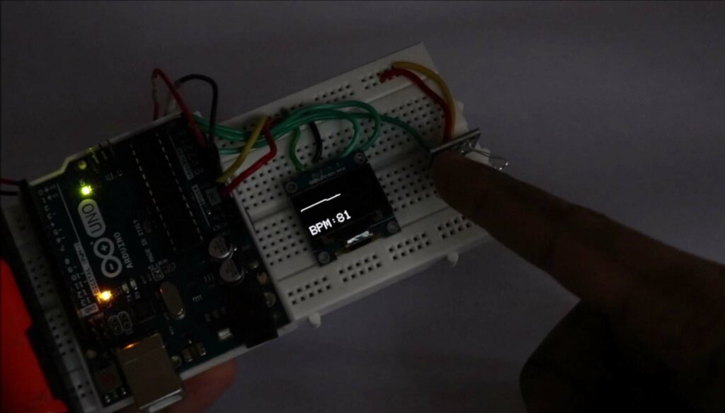
After uploading the code display starts to show BPM.
How to use?
To use this project you should avoid any direct light source as it interferes with the sensor giving inaccurate values.
Connect Arduino to the power supply via USB or batteries.
Place your finger on the sensor like shown in the below image and wait for some time to get the BPM.
You can compare it with your smartwatch or actual measuring device for accuracy.
Working Video of Heart Beat Monitoring System using Arduino
You can check this tutorial and working video of this project.
That finishes our project, Glad you made it till here Don’t miss checking our previous Game console project