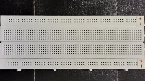
Breadboard Tutorial for Beginners
Before we dive into Breadboard tutorial for Beginners let’s first see How to use a breadboard properly as many are still doing major mistakes, Hope you are not the one!
- Breadboard is a prototyping platform for project builders.
- There are various types of Breadboard
- You can test your designed circuits without actually permanently soldering components onto PCB.
- You just have to hock up components into premade sections and that’s it.
- So Breadboards are called solderless PCB
Key points to keep in mind while working with breadboard.
- Layout on paper
- Power lines
- Stick labels on ICs
- Jumpers for extending connections
- No overhangs
- Test continuity using led
Layout on paper before putting on breadboard
The most crucial part for making any thing is that, you should have a clear vision of what you are making and same goes to breadboarding
So before putting all components together on breadboard to check whether your designed circuit does work or not you should have a layout of how the components should be placed
These can be called as breadboard diagram This avoids any misconnections or confusions while putting all things together
Also you don’t have to figure out while prototyping where should the component go in order have an efficient breadboard circuit
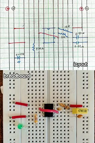
The handiest tool is a graph paper as it has pre-drawn equally spaced lines, Points with distance of 5mm are considered to two consecutive holes on breadboard
Also to make the layout readable use different colors pens to represent different things
An examples shows a stable oscillator using 555 timer IC on breadboard with its layout on graph paper
Where black color represents breadboard, blue color represents components and red represents jumpers
Power lines or power rails of breadboard
For powering the circuit on breadboard we have vertical lines provided for it
But there’s a catch to use them. Out of four verticals lines Most use of them two are reserved for positive supply and two for negative supply
The first one from left will be positive one then second will be negative one third will be positive and so forth will be negative
The arrangement is so because most of standard ICs (e.g. 74xx series) have VCC connection on right side and ground (GND) on left side
Jumpers join left power lines to right ones
But what if your circuit uses multiple power sources (like 5v and 12v) in that case you just have to remove the middle jumpers to disconnect upper portion from lower ones and now you use multiple voltages for your circuit

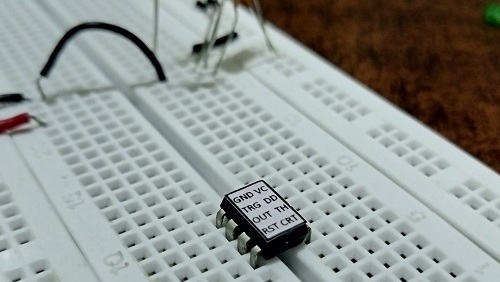
Stick labels on ICs
Sticking label actually means sticking a piece of paper over IC showing which pin stands for what
An example of 555 timer IC depicted in the following picture
This trick tremendously helps save time which would rather wasted in checking for pin function every time in the datasheet
You can create the label printing on paper or even writing them on paper if you can write that small
Sticking it with craft glue works pretty well. I have added a template for 8 pin DIP, 14 pin DIP, 16 pin DIP.
Details to use the template according to your need are given in the document which is template itself.
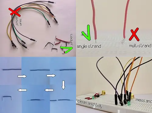
Jumpers for extending connections
These play crucial role in making the breadboarding process look neat and clean
Jumpers are used in connecting components when the legs of components fall short
Don’t get confused over jumper wires and jumpers
Jumper wires are those which have a specific length and have a pointed spear like structure at both ends which gets into sockets of breadboard
Jumper wires tend to make the process more messy and confusing
For creating jumpers the most recommended is single strand wire
Multi strand wire is never recommended as the wires tend to fray as we connect them
To use single strand of wire as jumper first strip off about 1cm of insulation from the wire, mark other end from the insulation as per requirement and cut the wire leaving again 1cm from other end and strip off insulation from other end
Now bend two exposed wires into L shaped and these will go into breadboard connecting any two horizontal sections or power the circuit
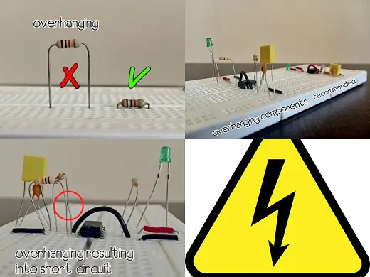
No overhangs on breadboard
To understand what overhanging components are, consider an example where you use a resistor if there is a gap between resistor and breadboard that means the component is overhanging
If most of components are overhanging there is chance of short-circuit as depicted in a picture
So to avoid these errors it recommended keeping the components as low as possible
Test continuity using led
Sometimes it may happen that the grippers which hold the legs of components gets widen up during course of time and they don’t anymore hold the components firmly resulting discounting in the circuit
And the most basic method to check these discontinuities is to use a multi-meter
But there is an alternative for it – LED
To use a led as continuity tester we first need to add a current limiting resistor
Snip off one, mostly the positive leg (as it will be easy to remember which is positive) and solder a resistor to it, use 470 ohm as it will protect LED from atmost 9v
Now it is ready to as continuity tester
The biggest advantage of using LED is that we can visualize the waveform in the circuit which greatly helps debugging
Just like a mini oscilloscope 😉
Hope Breadboard tutorial for Beginners was sufficient enough to make you a pro! Share this valuable info with your dummy friends who should have a look at this!