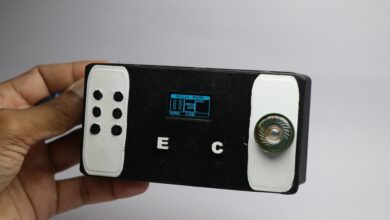
RFID based door lock system using Arduino
Hello readers in this article we will see how to make RFID based door lock system using Arduino.
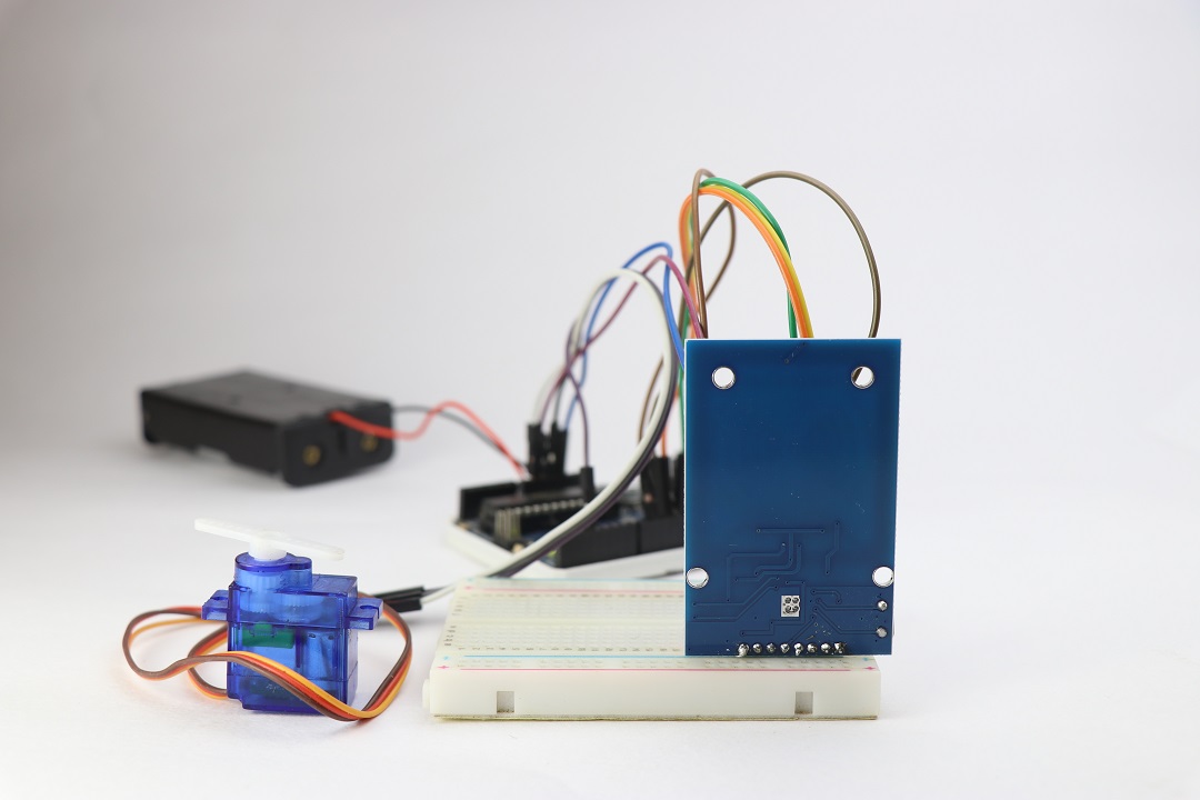
Here we will see the circuit for Automated door access based on RFID using Arduino.
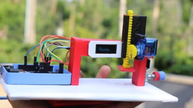
This circuit can later be connect to a door latch to take use of the servo movements.
This also can be adaptive in other applications too, Like for example kennel doors.
Here all that matters is the access card and the movement.
You may also find our project on Wireless Power Transfer Project interesting.
Some basic information on RFID Based door lock systems.
Generally, we all have doors and are operational with keys.
We lock and unlock the doors and each door has a lock and key.
Most of the door locks have a very unique pattern key so that it can’t be use on other doors.
Likewise, we can call these RFID tags as keys that store some information on micro chip
The data on the microchip is read by the reader and these are RFID readers.
You can compare these readers to the lock of the doors that read patterns of keys.
More technical information on RFID is below
To build this project we require some electronics and it’s given below
Note: Don’t miss to check out the working video given at the end.
Supplies Necessary
- Arduino Uno or Nano
- RFID RC522 module with tags
- Micro servo
- Haf breadboard
- Frew jumper wires
- Arduino IDE and programming cable
With these supplies In one place, we will see how this RFID RC522 works
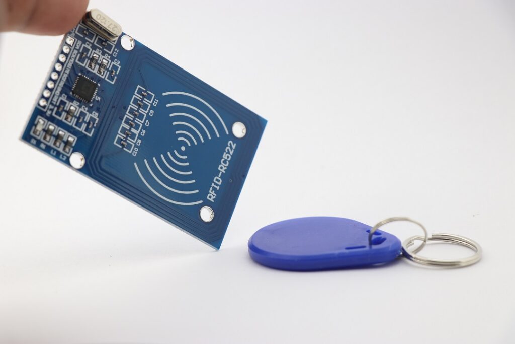
How RFID RC522 module works
The image of the RFID RC522 board can be seen below visual.
RFID means radio frequency identification.
These boards come with a tag.
Board is the reader and usually these works on the high-frequency electromagnetic field.
The tag does not need any power to work and is read by the reader.
Each tag comes with a Unique identification number.
Iit is to be pre-written on codes to be read by the reader
When a Tag is bought close to the reader.
High-frequency electromagnetic waves read the codes on the microchip on the tag.
If the ID on the tag matches the ID on the reader base, access will be open.
Either way, if it does not match access will be close.
Open access allows the movement of servo control.
These actions are done by the set of Arduino codes that allows for setting various parameters.
Actions like the time delay of servo motor movement can be set on Arduino codes.
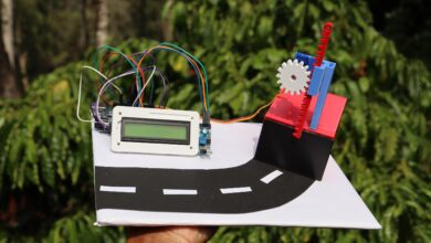
To begin with, we will start with the simple circuit for this project
Arduino RFID rc522 door lock circuit diagram
These will be the RFID Arduino and servo control circuit diagram.
We will make this even easier with some explanation for the rfid-rc522 wiring diagram
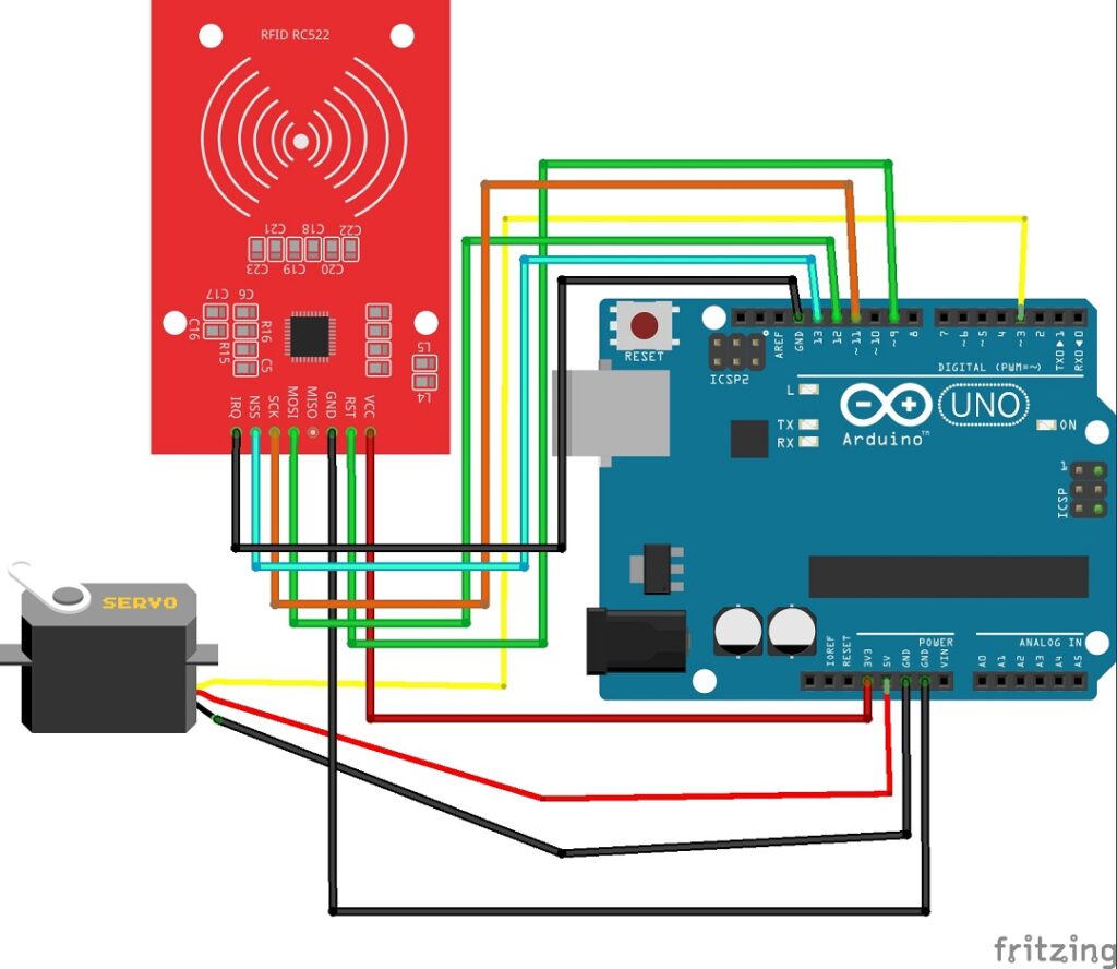
RFID rc522 pinout is above
It has 5 pins, pin with its connections with Arduino.
- Vcc to 3v pin on Uno
- Rst will go with D9
- Gnd to Gnd
- MISO will remain blank
- MOSI to D12
- SCK will go with D11
- NSS to D13
- IRQ will go with Gnd
Micro servo pinout with connections
Every micro servo has 3 terminals
Vcc, Gnd and signal.
Vcc and gnd will go with 5v and Gnd on Arduino Uno
Signal pin to D3 pin on Uno.
Now as we have the circuit ready we can upload the Arduino program
Arduino code for RFID based door lock system
rfid rc522 arduino servo motor Codes are Here
- You just open the IDE and paste these codes.
- You may also require the library to run the codes.
- rfid rc522 library is available here
- Just use the zip and include this zip on IDE
- To do so goto sketch-include library-add .zip library
- Use the library and click on ok
- Now hit on upload code.
- Note that we have to upload the code twice here
- First upload the code and open serial monitor
- Now bring the tag close to the reader, you will receive a UID of the tag.
This UID of tag should be paste on the code area as shown below
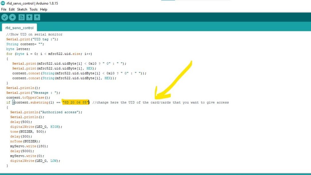
These UID on unique id is different for different tags use yours.
Now you can again run the Arduino code again
After you complete the upload our project is ready to use.
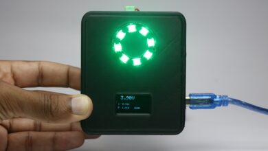
I will be using the power source from Arduino itself.
Now bring your tag close or just the reader board.
The servo will move, and you can change the servo delay parameter as per your needs.
If you want to check the working of this refer to the video below
Watch the working of this circuit in this video
Now some interesting factors about our sponsor
About Our sponsor PCB WAY
PCB WAY has been offering high-quality PCBs for creators like us at very budget-friendly prices so that we can build interesting projects.
They are now offering FR-4 & Aluminum boards along with their advanced tech PCBs like Flexible & Rigid-Flex boards, Rogers, and HDI at a very reasonable price.
More details are given below
They always come up with some competitions.
Participate and win a Raspberry Pi pico try your luck Click here
We are very happy to inform you that we have Technical cooperation with FreeCAD and kicad
We also have some latest plugins on Kicad check it out.
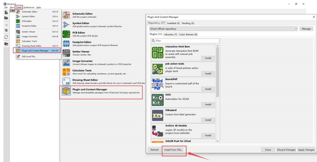
Check the details for freecad and Kicad here you will definitely like them.
Thanks for showing interest in our project, Check our other projects also you will definitely like them.