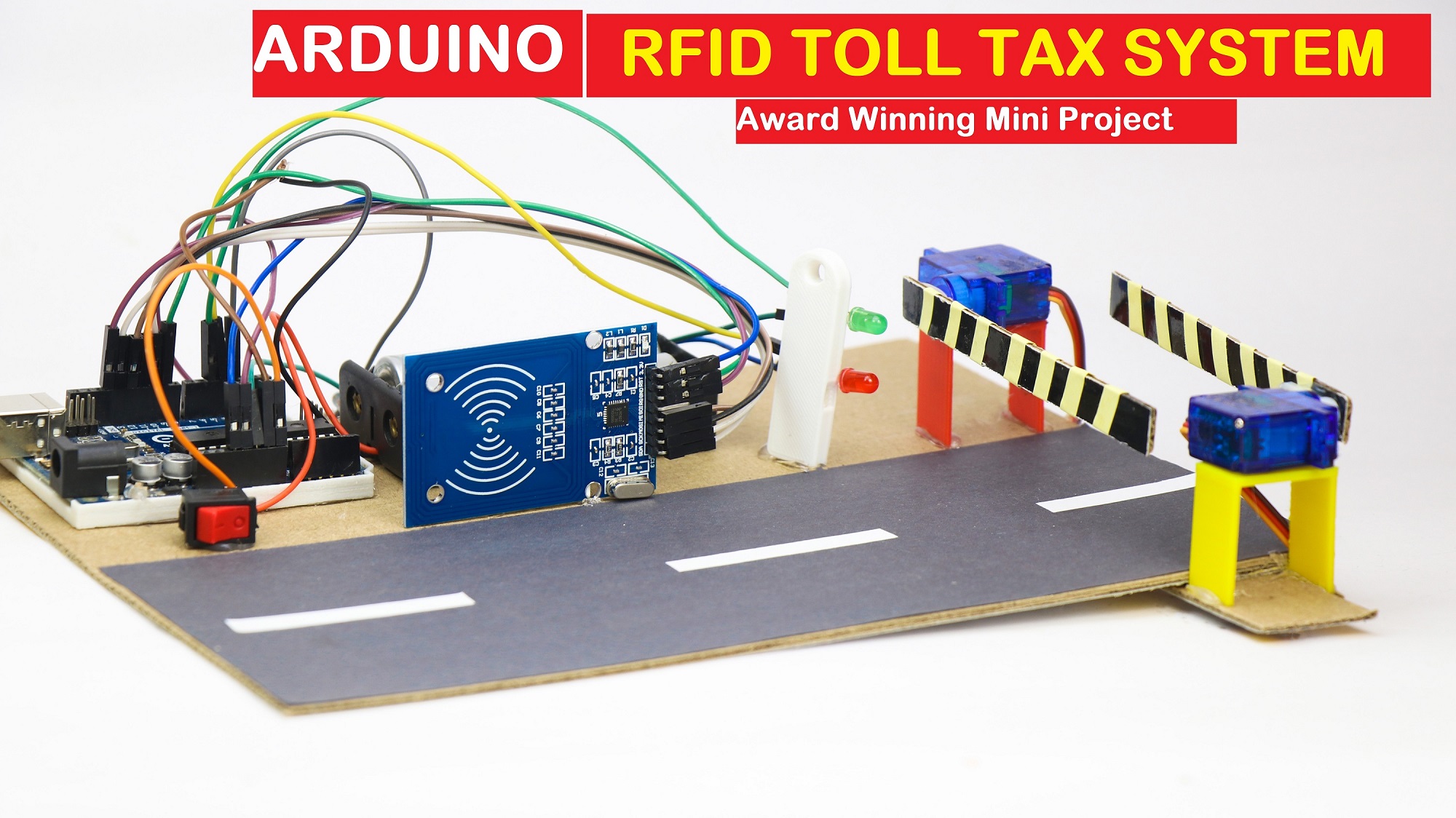
Toll Collection System using RFID and Arduino
Hi readers in this article I will show you how I made this Toll collection system using RFID in a very easy way.
I have given a Circuit Diagram, Codes, and a working video of this project in this article.
I have made a working prototype of the actual toll gate collection system.
In the actual system, the tags contain recharges here I’m replacing recharge with just access.
You can present this project as an engineering project as it is built considering real-world applications.
Note: You might also be interested in our Ultrasonic toll tax barrier project
What is an Automated Arduino RFID Toll Tax collection System?
RFID toll tax collection system using RFID and Arduino is a type of automated toll collection system that uses radio frequency identification (RFID) technology to identify and charge vehicles for using toll roads.
The system consists of RFID tags that are attached to the vehicles, RFID readers that are installed at toll plazas, and an Arduino microcontroller that acts as a gateway between the RFID reader and Servos(gates).
When a vehicle passes through the toll plaza, the RFID reader reads the RFID tag on the car and sends the data to the Arduino.
The Arduino then uses the data to retrieve the necessary information from the central database, such as the toll fee and the vehicle owner’s account balance(in actuality).
In our project, the RFID reader checks if the access is enabled or not for the particular tag
If the vehicle owner has sufficient balance, the Arduino deducts the toll fee from the account balance and opens the toll gate.
If the balance is insufficient, the Arduino denies access and alerts the vehicle owner to recharge the account.
Overall, the RFID toll tax collection system using RFID and Arduino is a fast and efficient way to collect toll taxes without the need for manual intervention, leading to reduced traffic congestion and increased revenue for toll road operators.
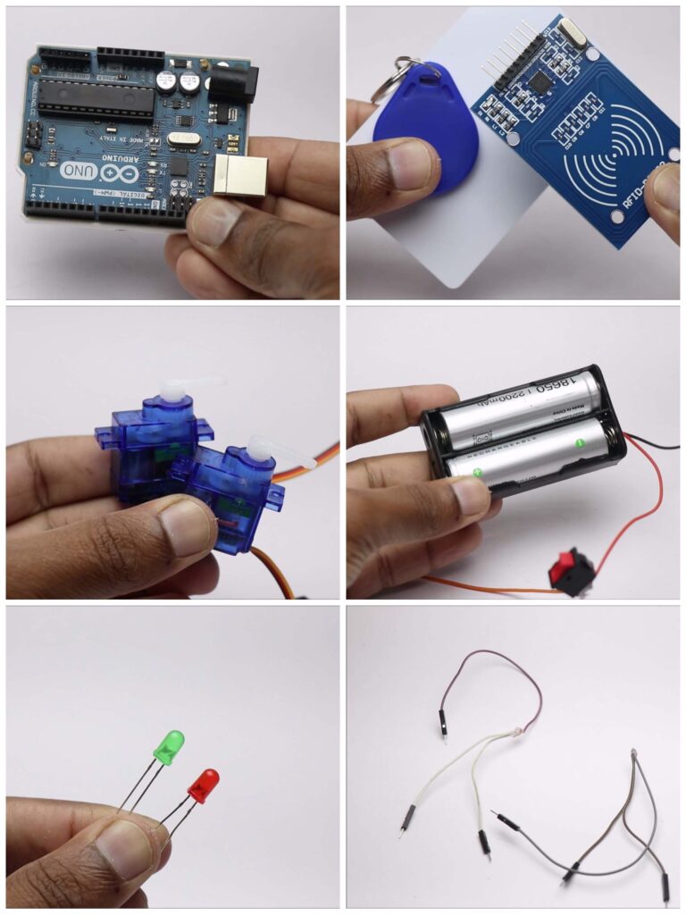
Materials Required
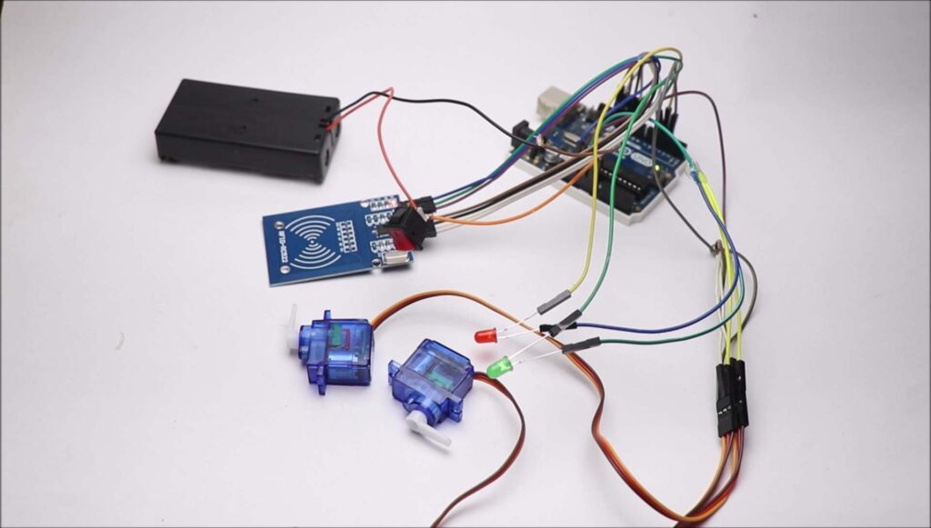
These are the materials required to build this project
- Arduino Uno Project kit from Amazon
- RFID sensor Module
- Micro Servo bought
- Lithium Ion batteries with holder
- Red and green Led
- Jumper wires
Note: I have modified jumper wires so that 2 micro servos will go to only one signal connection(in the last image)
As an amazon associate, I may earn from qualifying purchases at no extra cost to you.
Apart from these components, you might need a piece of cardboard and colored paper to make a road.
Arduino Ide and programming cable is a must as you know.
Circuit Diagram for Toll collection system using RFID
Here is the circuit diagram which makes this project.
I have given a step-by-step explanation of how to make connections between different components.
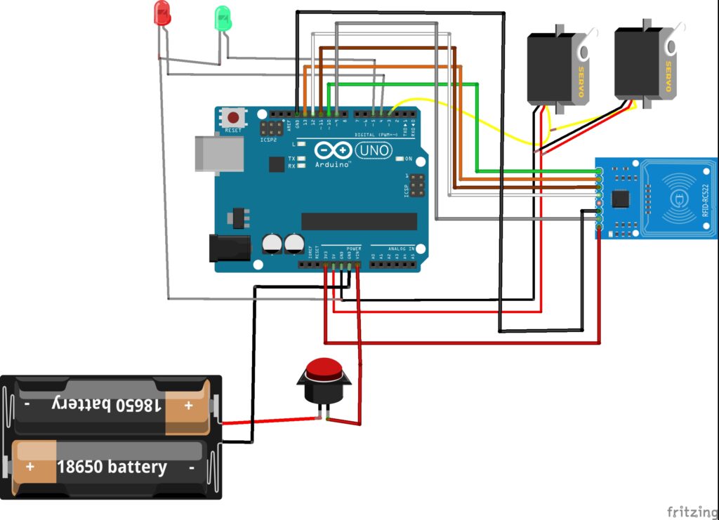
We will start with RFID sensor module.
- Pin with Arduino connections
- Sda to D10
- Sck to D13
- Mosi connects to D11
- Mi with D12, Gnd to ground, Rst to D9
- 3.3v power pin to 3.3v on Arduino
Green and red led negative pins to gnd on uno board.
Positive pin of Red to D4 and Green to D5.
Micro servo has 3 terminals, power and gnd to 5v and Gnd, signal to D3.
Arduino Code for RFID based automated toll collection system
You can copy and paste these codes on your Arduino ide, later you have to follow the below instructions.
Arduino Codes For the RFID toll tax system are here
Once your code is upload to the board you can follow the steps below.
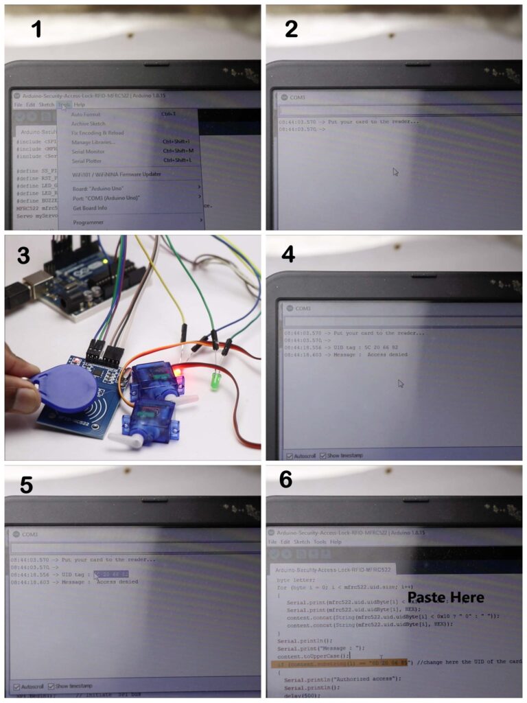
Open the serial monitor by going to menu->tools->serial monitor
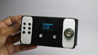
Open serial monitor there it shows a message put card to the reader
Now you can just tap the card/tag that you want to access.
You will get a code after you tap the card, copy this code
Come back to the code and paste this copied code on the default set code(refer image 6)
Now again upload the code and after its done, our circuit is ready for testing.
Checking The Circuit
After the connection is complete check the circuit
You might need to connect the power from the battery.
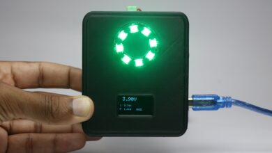
Tap the registered tag and if the green light and servo move the circuit is correct
Different tag red led glows
Finishing
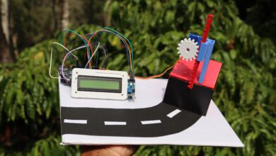
We can now add all the electronic components on cardboard.
To make the road look alike I cut white strips of paper and stick them to black paper
This paper will be glued to cardboard.
Now use super glue to add all other electronics.
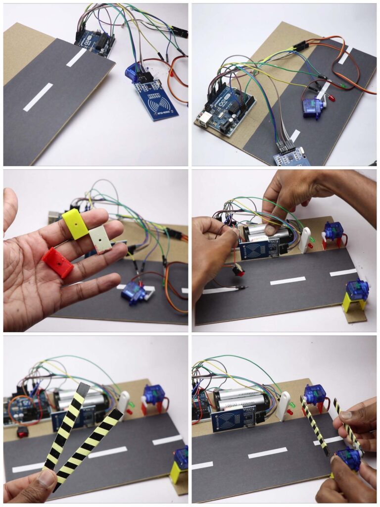
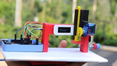
I had some of the frames that were 3d print.
I made use of these as supports for my electronics
You can use cardboard pieces for the same purpose.
For the gate, i cut a strip of cardboard.
Paint with black and add yellow side strips and stick these to the horns of the servo
These complete our project model and is ready for use.
This is how our project looks like
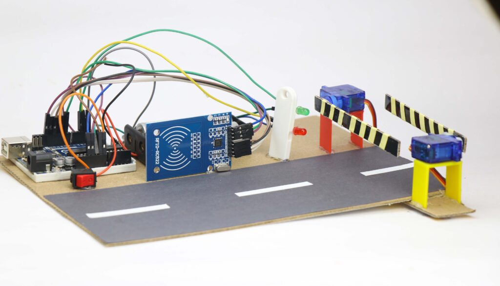
For a working video, you can check here, Hope you will build this project.
If you have any questions ask me in the comments I will answer you shortly.