Modifying a 775 DC Motor to Double shaft using 3D Printed Parts
Hi readers in this post I will show you Modifying a 775 DC Motor to something extraordinary.
I have provided all the step by step instructions and STL files for building this.
If you are a hobbyist or electronics projects maker you would have worked with dc motors.
These DC Motors come in various sizes and the usage depends on the type of application it is used in.
For example, a toy remote-controlled car uses a toy dc motor whereas rc boat used a 180 motor.
In cordless drills, they use 775 motors.
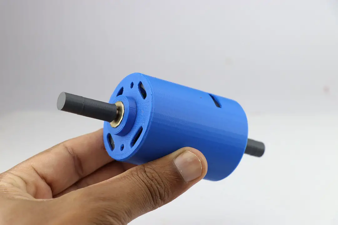
So in this project, I will be converting a 775 dc motor to a dual-shaft motor
Now you may think about what is the need for converting and where it is useful, here is the answer.
Note: I have also given a working video of this project, don’t miss to check it out.
What is a dual shaft motor?
A dual-shaft motor or also known as a double shaft motor is a type of electric motor that has two shafts extending from both ends of the motor’s housing.
These two shafts can be used for driving two different mechanisms.
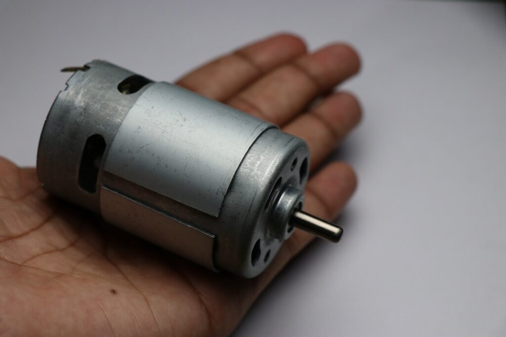
From the above image, you see what a dc 775 dc motor looks like with a single shaft.
This works well at the moment but as time passes by the metal body starts to rust.
Why make a dual shaft motor?
There are 2 reasons behind making this project
One is as I have 3d printed the body there is no question of Rusting as you might know these 775 motor body gets rusty.
As it is made from PLA there will be an overall loss in the weight of the motor that adds to the increased efficiency of the motor
Secondly imagine a project where you have to drive 2 mechanisms, using a double-shaft motor will save space and money.
In terms of efficiency, you can expect more efficiency by using these rather than using 2 separate motors.
Double shafts are more stable in comparison with single shaft
The advantages are many so what is stopping you to build this today?
Supplies Necessary
- 775 dc motor
- A flathead screwdriver and a plier
- 3d printer and PLA filamentt
- Superglue
- 7.4V battery pack for testing
- The speed controller is optional
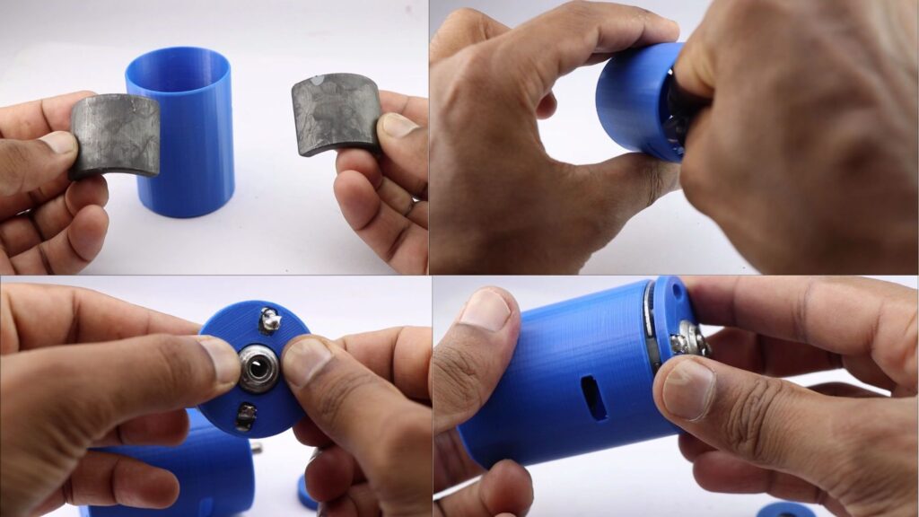
Disassembling a DC motor
Since we are migrating into a 3D-printed body we have to remove all the inside components from the existing motor.
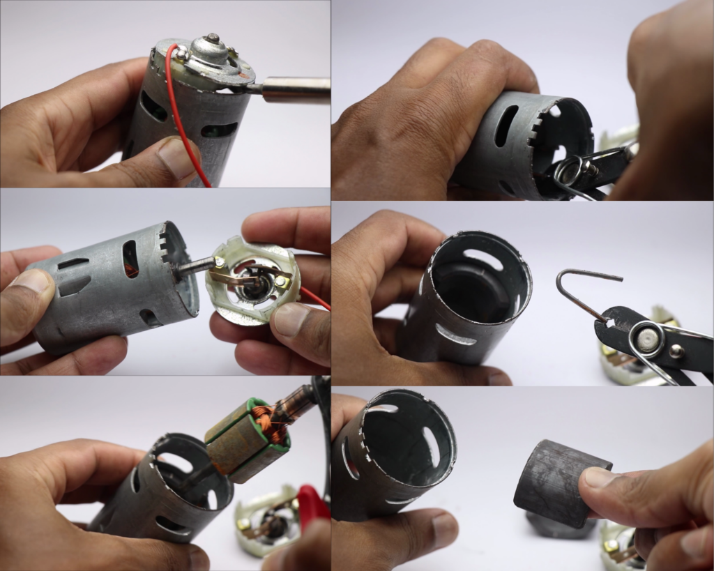
This can be done very easily, follow these simple steps.
Make sure you start by removing the supports given at the base first.
Gently insert a screwdriver and take out the base.
Using plier you can pull out the rotor part.
To remove the magnets first remove the V shape pin.
After doing this you can remove the magnets by hand.
Keep the magnets away from metal substances as this attract them.
Design of 3D printed case for 775 motor
I have designed this project using tinkercad application, it is a web application and there is no need to download or install it.
It took me several hours to come up with the design and here are the final design stl files.
STL files for 3d Printing are here
Once you have the stl you can open a slicing software and place the parts.
Note that no part needs rafts or supports, kindly use the same object placements as I did.
I did not want to fill this post with full of images so I have made a collage of steps that’s easier to understand.
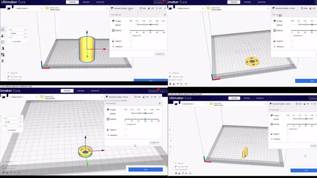
The above visuals show you the settings I have used, you can print all the parts at once also.
I printed them in blue PLA filament, the choice of color is left up to the taste of the maker.
After slicing you can export the design to the printer and print the parts.
Here is the overview of all parts of the phase of 3d printing.
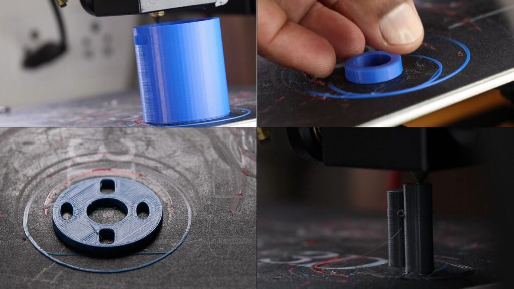
These are all the parts that we will be printing, after the printing process we can move to other steps.
3d printed parts do not need any cleaning as we did not use any supports at the time of printing.
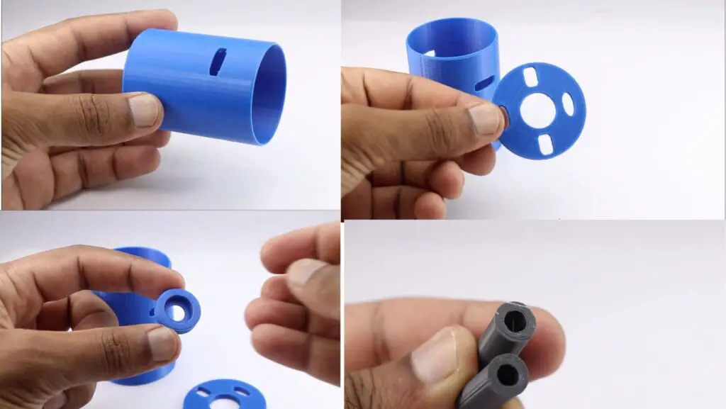
After you have these parts ready we can work with the assembly.
Assembling components inside a 3d printed case
To begin with, we will start with magnets.
You have to work on one magnet at a time, we will start by placing the magnet inside the case after adding a few drops of super glue.
You may need to wait for some time until the glue is completely dry and move on to work with another magnet.
After we have the 2 magnets inside the case we can work with the base part.
I did not replace the base part(metal) since we have a few parts here that can’t be replaced by 3d printing.
The main factor here is friction, the metal base(by default) has a metal slot inside which the shaft rotates.
It also has a brush that will be in contact with the rotor.
After considering all these factors I made a decision not to replace this base instead make a case and join them together.
You can see the process I used to work with the base.
Place the rotor and glue the base as in the visuals.
Finishing the Motor
The top part of the shaft undergoes friction too
To fix this issue I scavenged this nut kind of thing from the previous dc motor.
The 3d print part was made so that this nut would fit inside well.
Just use a drop of superglue.
Now you can add the 3d print shaft to the metal shaft, here you might need to use some force.
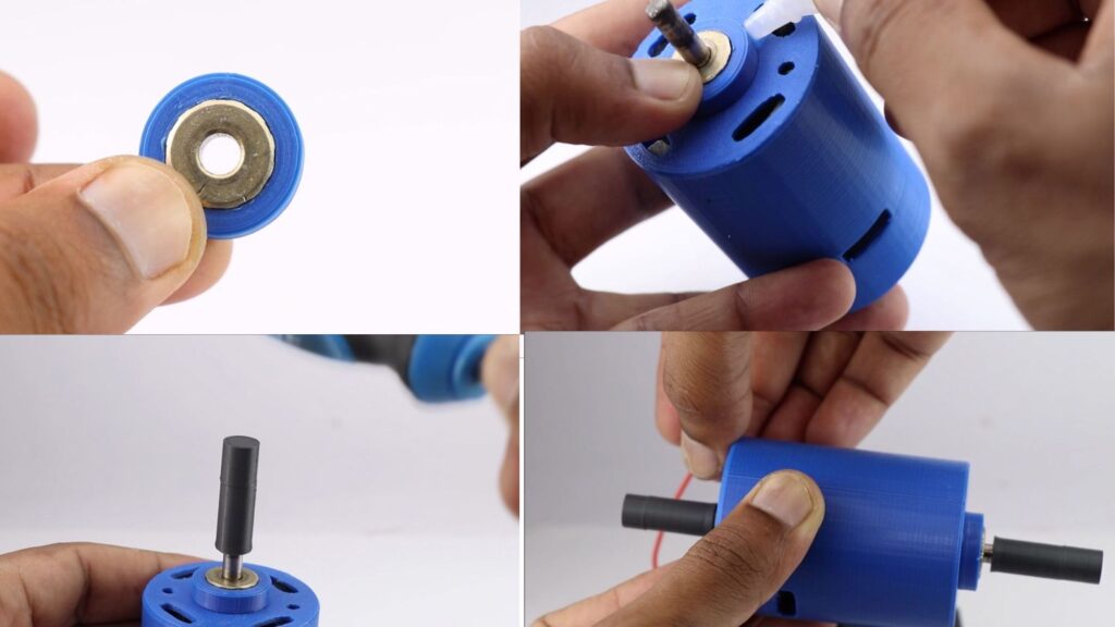
This was all about Modifying a 775 DC Motor to a double shaft.
You can run this motor connecting to a 7.4v dc power source. Use a speed controller if necessary.
Hope you will modify them as I did, you can watch the working video here.
You might also like our previous post on Arduino OLED Clock without RTC