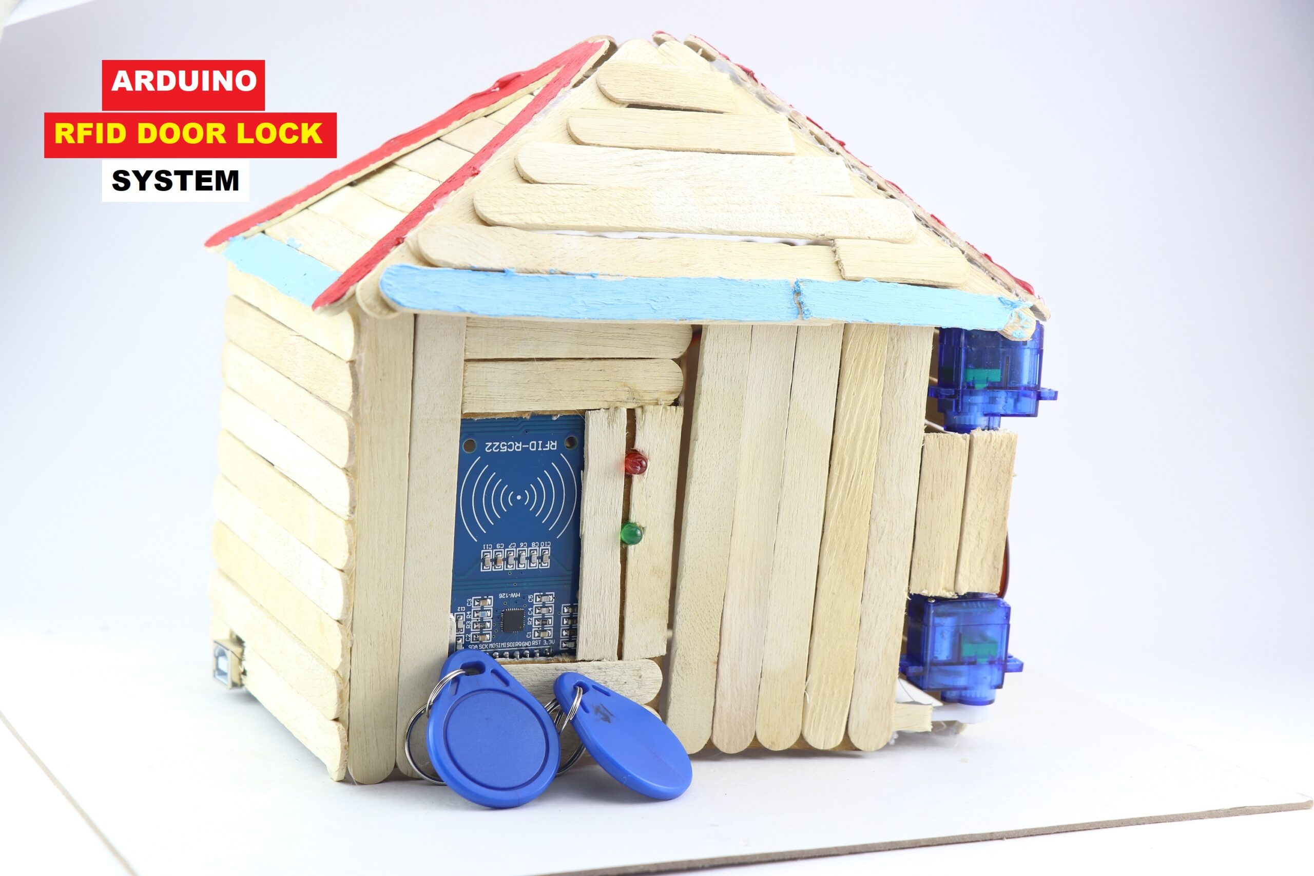
Arduino RFID Door Lock System for Home
Hi, readers in this project I will show you how I made Arduino RFID Door Lock System for the door in your house.
The project is very simple to build and I have given all the Arduino codes for the servo and RC522.
The materials used to build this are easily available and you can get them online or offline.
Now you may wonder its working
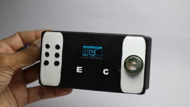
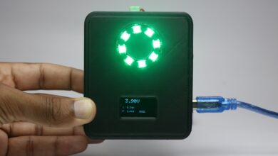
Bonus: Check out this amazing OLED display clock project and Don’t miss to read till the end for a surprise!
How RFID door lock system works
Each Authorized user is provided with an RFID tag/card.
The unique identifier of each RFID tag/card is registered in the Arduino’s memory.
This is typically done by scanning the RFID tag/card first and storing its unique identifier(UID) first in the database within the Arduino.
The Arduino codes are written in such a way that when a registered tag is tapped on the RC522 module the servo works with green led glowing.
Whereas when the unregistered tag is tapped the servo does not work instead the red led glows.
This simple principle was incorporated in the opening and closing of doors in the house.
This smart door lock for your home works with this simple logic and now we will see the components necessary.
Supplies to build RC522 smart Door system
The supplies necessary to build this is shown on the visuals along with their names below.
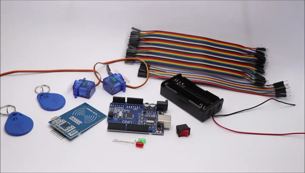
Note that in the visual above I have shown a battery holder and a switch.
This is optional, I have used the default USB power supply for powering Arduino.
If you are doing the same as me no need to get the battery holders and a switch.
- Arduino Uno works best for this project
- RC522 RFID Reader with tags x 2 (I bought an additional tag)
- Plastic gear Micro Servos
- LEDs
- Jumper wires
- Popsicle sticks
- Paper glue and hot glue
RFID Door Lock System using Arduino Circuit Diagram
The circuit connections may seem a little complex to you! But in reality, it is very easy.
I will go through the connections of each component so that you can easily follow the circuit.
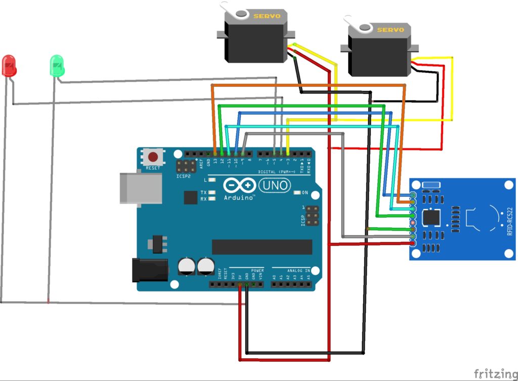
I will split the circuit connections into 3 components.
First is the RFID or RC522 module
It has 8 pins in our project we are using 7 of them.
Start by connecting jumper wires SDA to D10, and SCK to D13.
MOSI to D11,MISI to D12.
Gnd to Gnd, Rst to D9 , 3.3v to 3.3v of Arduino.
Second is Micro servo
Here the signal pin of both the servo is connect to the D3 pin.
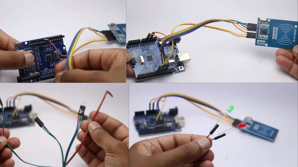
I have custom-made the jumper wires to that we are connecting gnd of 2 servos and 2 LEDs together
Here is the view of the jumper wires that were able to minimize the jumpers.
Third is the LED
The negative side of the LED is connect to the GND of Arduino while the other legs of green to D5 and red to D4.
This is how your circuit will look after the connections.
RFID door lock system using Arduino code
Here are the codes for RFID door lock system using Arduino and RC522
Connect your Arduino to the computer using the cable and open IDE.
Select the type of board and upload the code.
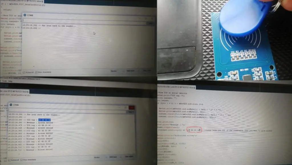
After this open the serial monitor and you will see a message put your card on the reader.
Tap the tag that you want to register, and copy the UID.
Paste this UID on the code and reupload the code again
Now you can test the circuit by tapping the registered tag on the reader.
You will get the green led glowing and the servos working.
When you tap the wrong tag you will see a red led glowing that states the incorrect tag.
Since we have electronics ready we need housing to install all these
I will be making a popsicle house that resembles a real house
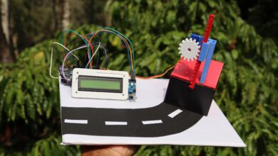
Making House for RFID door lock project
To make a closure for the electronics and to make the project more appealing I made a house.
This was made using popsicle sticks, and it is very easy to build.
Make squares by combining popsicle sticks and gluing them with paper glue.
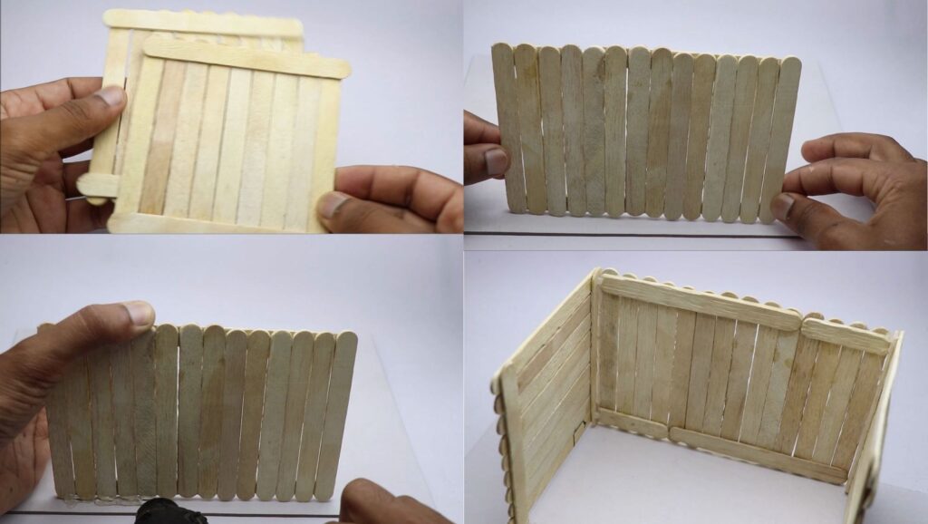
I will be using hot glue to stick these frames to the cardboard base.
To supply power to the Arduino board I will use a USB power supply.
Since we are assembling all the electronics inside make a slot for the Arduino power port.
Use a small amount of hot glue if necessary to keep everything in place.
Paste the other sides of the wall and allow it to dry completely.
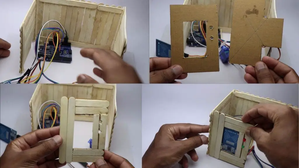
To hold the RFID reader I made a small template from cardboard.
Place the popsicle sticks on this template and glue them together.
Use slightly hot glue to stick the RFID module to this frame.
LED was also insert into the slots, Later paste the entire frame to the base.
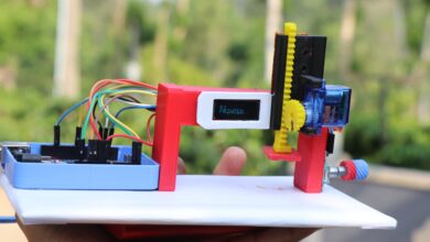
Building Door Mechanism
This is an important part of this project
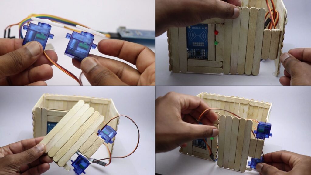
We Have 2 servos that will work at the same time.
These servos are on these doors, I have made a trial and come up with this final design.
Just test the servos on which direction they are moving first, and later paste them to the door.
Again check for the movements of the door and paste it to the wall.
End of the step you have all the electronics installed.
Now to finish this model we need a roof.
One thing here is to have the accessibility to work on the electronics if necessary we need to have an openable roof.
I made the roof using the same method I used to make walls.
The only difference is these have triangular shapes.
Make sure the length matches the size of the walls.
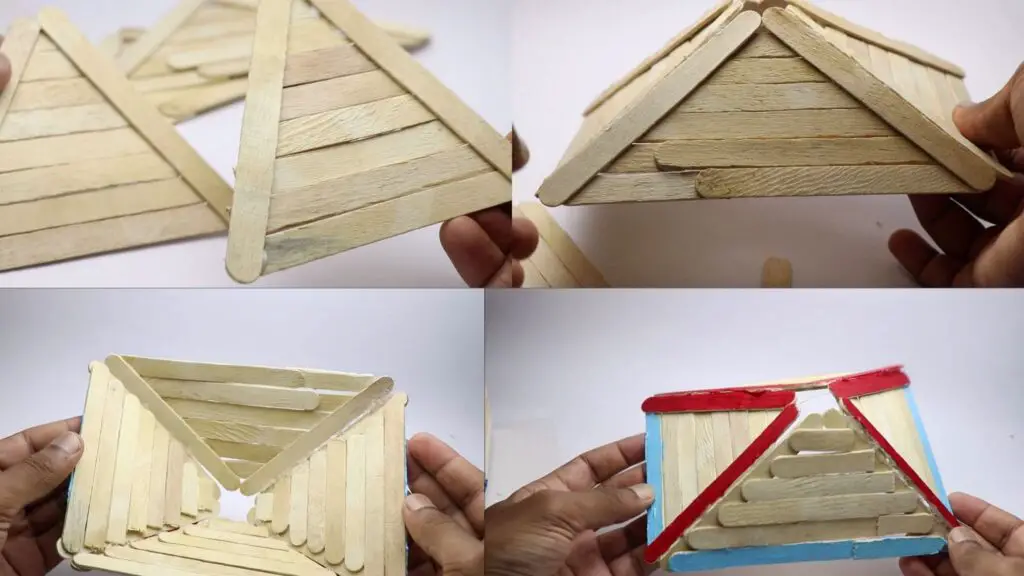
You can paint the roof with your favorite color, but it looks cool with the default color.
Since it fits without the need for any glue gently place the roof on the walls.
I had additional wires that I had to glue to the roof so that it won’t be visible when the door opens.
This completes the project now let’s see how to use this project.
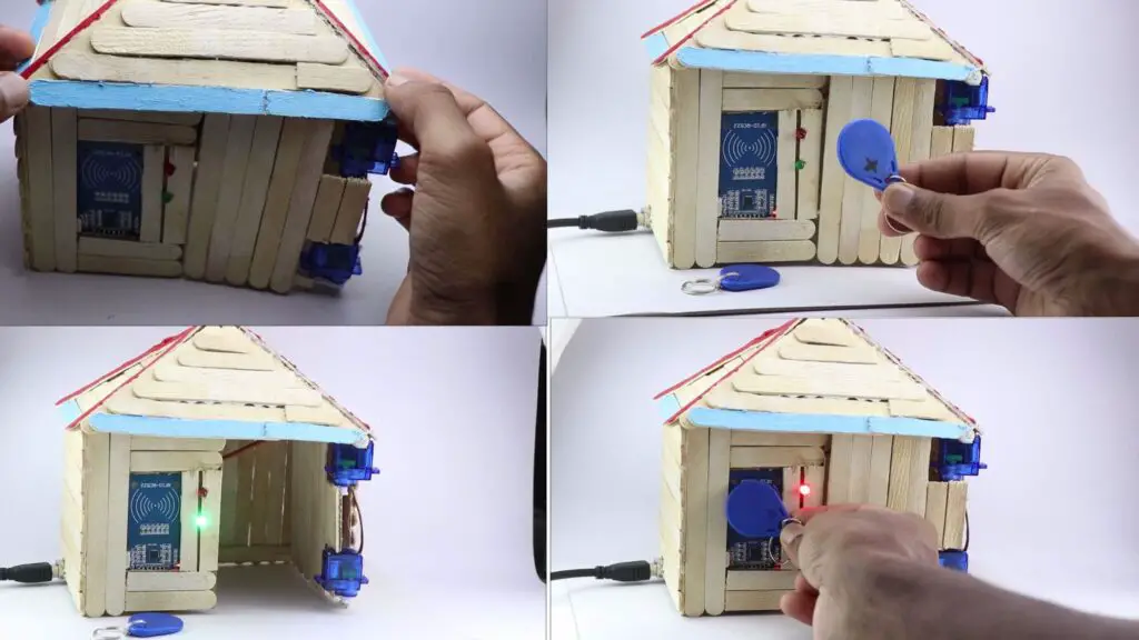
How to use RFID door lock system
I have 2 tags one is registered already and the other isn’t.
I have marked the accessible tag so it is easy to identify.
Imagine that it is your home and you want to open the door.
Just tap on the RFID board and the servo opens with a green light.
This opens the door for some time and then automatically closes.
When you tap the unregistered tag the door will not open instead a red light shows up.
Advantages and Disadvantages of RFID door lock system using Arduino
For every creation or technology there are a few limitations as well let us see those too.
Advantages of RFID Door Lock Systems
- RFID (Radio Frequency Identification) technology offers a good level of security compared to traditional lock systems as It uses unique identification codes.
- RFID door locks provide a convenient and contactless way of granting access.
- Users can simply swipe or tap their RFID cards or tags near the reader to unlock the door.
Disadvantages of RFID Door Lock Systems
- Implementing an RFID door lock system can be more expensive compared to traditional lock systems.
- The cost includes the RFID readers, cards or tags, and associated software.
- Like any electronic system, RFID door locks are susceptible to technical malfunctions or issues.
- This can include reader failures, card or tag damage, or communication errors.
- If an RFID card or tag is lost or stolen, there is a risk of unauthorized access to the secured area.
Working video of RFID door lock system
Here is the video that shows the working of this project
You can build this project for your engineering projects, if you have any questions ask in the comments.
Don’t miss to check our other cool projects on raspberry pi check here
Where can you get good-quality PCBs?
The answer is at Next PCB!
HQ NextPCB and HQ Online are the overseas trading brands of Shenzhen Huaqiu (HQ) Electronics Co. Ltd., a reliable multi-layer PCB manufacturer and assembly house.
Their capabilities include up to 32 layer boards, blind and buried vias up to HDI 3, custom stack-ups, full turnkey assembly and more via a smart quotation platform with dedicated one-to-one support.
Founded in 2009, NextPCB’s passion for fast, reliable, and affordable full-featured electronics manufacturing has driven NextPCB to innovate and modernize the electronics manufacturing industry.
NextPCB developed and maintains the software HQDFM, a groundbreaking tool for designers to analyze PCB Gerber files and detect design issues. Over 300,000 users around the world already choose NextPCB. Try them for your next design at HQ NextPCB.com and see how they can accelerate your workflow.