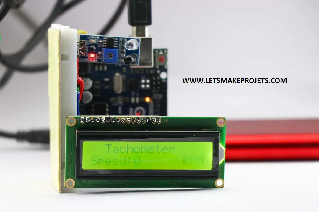
Make Tachometer using Arduino
Hey readers in this project we will Make Tachometer using Arduino which contains all the step-by-step instructions along with free Arduino tachometer code and Arduino tachometer circuit.
To begin with, let us have a look at few basic things about this project.
What is Arduino Tachometer
In general, Tachometer is an instrument/device to measure the rotation speed of objects which gives out values in RPM meaning rotations per minute.
This is a very common device used in automobiles to measure various RPMs.
So now you may think why make rather than buy?
It is a joy to make things from scratch because we learn a lot of important things and other reasons being cost.
As this tachometer comes in a high price tag we are using Arduino to make an inexpensive version other names for this is Arduino RPM Meter.
Please note that the Arduino tachometer and Arduino RPM meter are the same terms in use here.
How Arduino RPM Meter works
Here we are using an IR sensor module to detect rotation, the logic here is very simple.
Before measuring the disc RPM we need to add a white/black stripe to the disc which serves as a guide for the IR sensor.
Since the Infrared module sends IR pulses from one diode and receives from one diode the strip serves as an obstacle.
Due to this Obstacle, there will be some delay between sending and receiving signals.
It measures the time taken for that strip to complete one rotation.
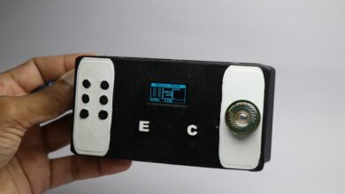
Hence this will be further process by a set of codes and sent for visualization on the LCD display.
Note: If you want to check working Don’t miss checking video given at the bottom.
Materials for Arduino based Optical Tachometer
Can you believe only these are materials to build this amazing project?
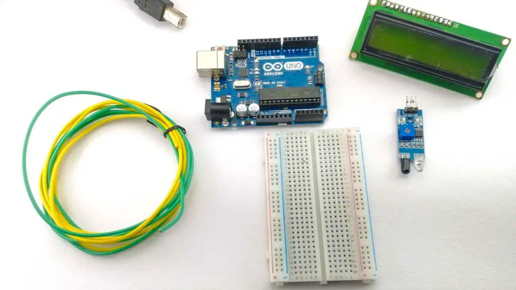
The materials are
- Arduino Uno
- Programming cable
- Infrared sensor
- Breadboard
- Single stranded wire
- 16×2 LCD display module with I2C module attached
Apart from this, you need a motor with a propeller or disc with a white or black strip.
To begin with, make sure you have all these supplies ready, here are few things you need to make a note of before making the circuit.
I made use of single-strand writes instead of jumper wires as it saves lots of space.
Using strand wires makes the project looks clean rather than being messy.
Follow this circuit to get all the components together.
Tachometer Circuit Diagram using Arduino
Use this diagram to make connections, if you are having trouble following this visual check the detailed explanation of the same below.
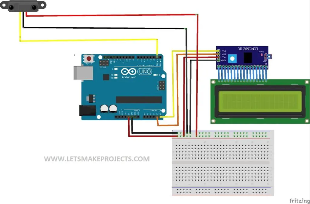
I have made this circuit diagram using fritzing software which is very flexible in making such circuits.
I recommend using a small breadboard for this project as it makes it compact.
IR sensor connections
It has 3 terminals 2 for power supply and one for the signal.
We are connecting Gnd and Vcc to breadboard negative and positive rails.
Signal pin(out) is connect to the D2 pin of the Arduino board.
LCD display module connections
This LCD display has an I2C module attached to its back so here we have 4 terminals.
Like previously said connect Gnd and Vcc to breadboard negative and positive rails.
SCL and SDA to pin A5 and A4 of Arduino Uno.
Arduino Uno connections
Use Gnd and 5v pins of Arduino board to Power Breadboard Rails.
You can check for the same details in the circuit given above.
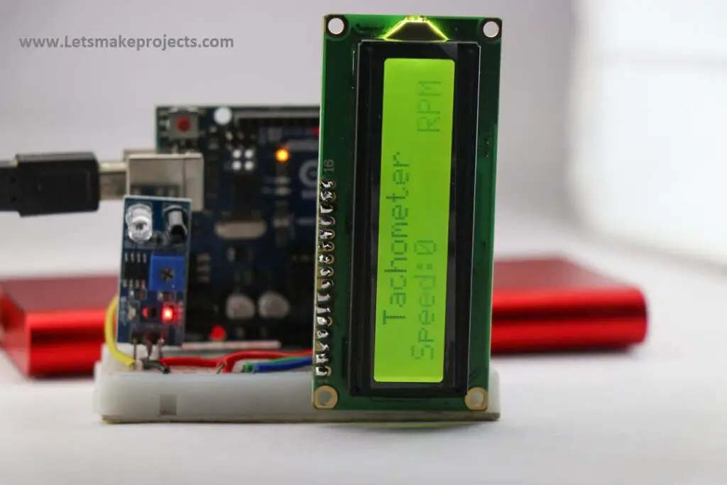
Building Tachometer using Arduino and IR sensor.
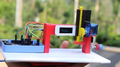
Once you make connections for more convince make a setup as in the image.
I am using an LCD display and breadboard as a stand so that the user doesn’t feel a bit tricky.
After we have this setup ready we can add some codes for its working.
I highly recommend you to make the same setup as shown in the below visual.
Arduino IR Tachometer Code
Use this Arduino CODE for Arduino Tachometer with IR sensor.
Once you open this you have 2 sets of codes, one is the i2c module scanner and the other is for the tachometer.
No need to have a headache by thinking about why 2 sets of codes are being given.
I2C scanner is for scanning the LCD display module driver.
Steps for uploading Arduino Tachometer Code
Connect Arduino Uno to the computer and open IDE.
Check for proper port numbers and select board types if this is not done already.
NOTE: If you don’t have I2C Library download and install from HERE
Once you have this library you can upload programs.
Use the I2C scanner code and upload.
This is done to check if the driver is sending signals to the LCD board.
Check serial port to verify if the module is being detected.
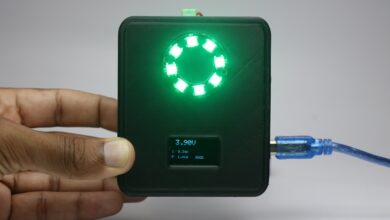
Now upload the Tachometer code, once it is done you will see a display module showing some texts.
If everything is fine IR module starts to blink.
Our project is ready for use!
How to use
Connect the power supply to Arduino, Here I used a USB cable connect to the power bank.
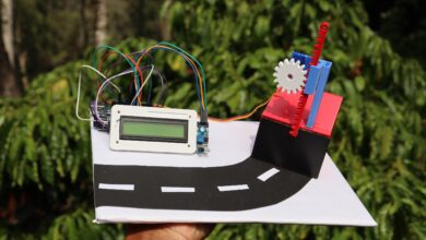
Attach a small piece of the adhesive tape to the disc/ propeller then attach it to the motor shaft and bring it in front of the IR sensor.
LCD display shows the reading.
Now we have made our Arduino based Optical tachometer ready for use, Check here for Video
That completes this tutorial, If you have any clarifications let me know in the comments.
If you like the Tachometer with Arduino project do not Miss checking this ARDUINO LCD GAME Project.